Supercharge Your Innovation With Domain-Expert AI Agents!

Jack contact and connector assembly

A technology for jack contacts and connector assemblies, which is applied to the parts, connections, electrical components and other directions of connecting devices, can solve problems such as affecting the use of connectors, occupying space for plugging, damage and deformation of jacks, etc., and achieves an improvement effect. , the effect of eliminating plugging resistance

Active Publication Date: 2015-10-21
CHINA AVIATION OPTICAL-ELECTRICAL TECH CO LTD
View PDF8 Cites 2 Cited by
  • Summary
  • Abstract
  • Description
  • Claims
  • Application Information

AI Technical Summary

Problems solved by technology

[0003] The Chinese invention patent with the publication number CN101106230A and the announcement date of January 16, 2008 discloses a plug-in sealing structure for underwater electrical connector contacts. A drainage groove is set between the insulating sleeve on the top and the socket insulator, that is, the mating surface on the socket insulator to achieve the purpose of draining the water between the two when the plug and socket are inserted, although such a mating sealing structure can Drain the accumulated water between the plug and the socket, but there is no way to discharge the water that enters the socket socket contact before insertion, so that the water in the socket contact occupies a certain insertion space, resulting in resistance to insertion Very large, it is difficult to insert into the insertion position, that is, the insertion end of the pin contact is located at the bottom of the socket of the socket contact, which seriously affects the use of the connector, and the forced insertion will easily cause the pin The plug-in end of the contact or the socket of the socket contact is damaged and deformed, and even the seal fails and the conductive connection cannot be realized, and it cannot be used normally

Method used


Image

  • Jack contact and connector assembly
  • Jack contact and connector assembly
  • Jack contact and connector assembly

Examples


Embodiment Construction

[0019] The connector assembly of the present invention will be described in detail below in conjunction with the accompanying drawings:

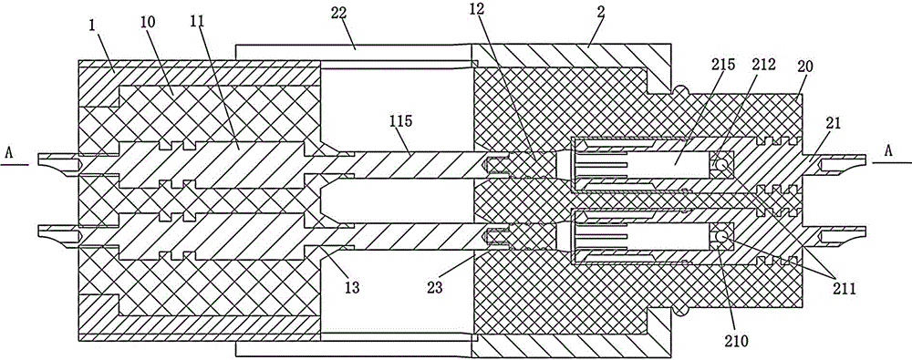
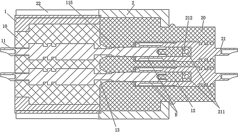
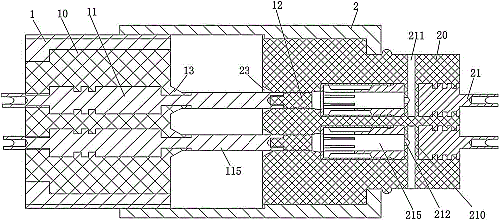
[0020] Embodiment 1 of the connector assembly of the present invention: as Figure 1-3 As shown, it includes a plug and a socket, wherein the plug includes a plug housing 1, the plug housing 1 is a cylindrical shape extending left and right, its outer peripheral surface is provided with connecting threads, and a plug insulator 10 is fixed inside, and the plug insulator 10 is fixed inside. The pin contact 11, the pin contact 11 extends in the left and right directions, the overhanging section of the pin contact 11 protruding from the right side of the plug insulator 10 is the plug end 115, and the right end of the plug end 115 is provided with a sealing insulation 12.

[0021] Socket comprises socket shell 2, and socket shell 2 is also the cylindrical shape that extends left and right, and socket insulator 20 is fixedly arranged in socket sh...


PUM


Abstract

The present invention provides a jack contact and a connector assembly. The jack contact comprises a contact body, wherein the contact body is provided with a jack, the contact body is provided with through channels which are communicated with the jack and the external part of the jack contact and are used for penetration of drainage channels. The drainage channels in insulation coordination with the jack contact can penetrate through the through channels, so that communication between the external part of the jack contact and the internal part of the jack can be achieved, when a plugging end of a pin contact is plugged in the jack, water in the jack can drain through the drainage channels penetrating through the through channels, thereby eliminating plugging resistance and protecting the jack contact and the pin contact.

Description

technical field [0001] The invention relates to a conductive connection device, in particular to a socket contact piece and a connector assembly. Background technique [0002] With the development of submarine power transmission, the application of underwater connectors is becoming more and more extensive, and its role is becoming more and more important. The main technical problem of the underwater electrical connector is how to ensure the conductive seal, especially the problem of ensuring that there will be no water accumulation between the plug and the socket during the insertion process. [0003] The Chinese invention patent with the publication number CN101106230A and the announcement date of January 16, 2008 discloses a plug-in sealing structure for underwater electrical connector contacts. A drainage groove is set between the insulating sleeve on the top and the socket insulator, that is, the mating surface on the socket insulator to achieve the purpose of draining...

Claims


Application Information

Patent Timeline
Patent Type & Authority Applications(China)
IPC IPC(8): H01R13/523H01R13/46
CPCH01R13/46H01R13/5227H01R13/523
Inventor 李思行张磊张晓光孙晓龙
Owner CHINA AVIATION OPTICAL-ELECTRICAL TECH CO LTD
Features
  • R&D
  • Intellectual Property
  • Life Sciences
  • Materials
  • Tech Scout
  • Unparalleled Data Quality
  • Higher Quality Content
  • 60% Fewer Hallucinations
Learn More