
Methods of determining initial position of rotor

A technology of rotor position and rotor, applied in the direction of electronic commutator, control electromechanical transmission device, electronic commutation motor control, etc., can solve problems such as sensor failure

Active Publication Date: 2015-10-21
DEERE & CO
View PDF4 Cites 9 Cited by
  • Summary
  • Abstract
  • Description
  • Claims
  • Application Information

AI Technical Summary

Problems solved by technology

Sensors often fail in harsh environments such as excessive ambient temperatures, ultra-high speed operation and other adverse or heavy load conditions

Method used

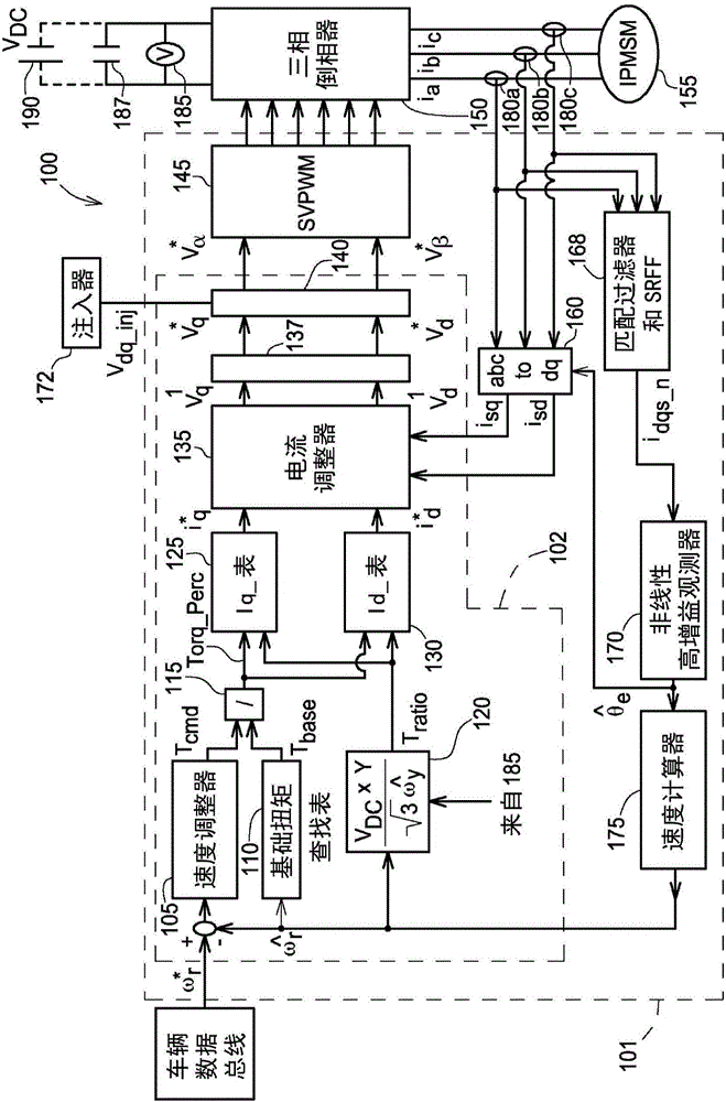
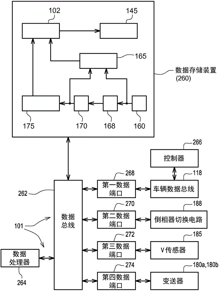
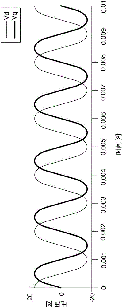

Image

  • Methods of determining initial position of rotor
  • Methods of determining initial position of rotor
  • Methods of determining initial position of rotor

Examples


Embodiment Construction

[0017] Various example embodiments will now be described more fully with reference to the accompanying drawings that illustrate some example embodiments.

[0018] Accordingly, while the exemplary embodiments are capable of various changes and alternative forms, the embodiments of the present invention are shown in the drawings by way of example and will be described herein in detail. It should be understood, however, that there is no intention to limit example embodiments to the particular forms disclosed, but on the contrary, example embodiments are to cover all modifications, equivalents, and alternatives falling within the scope of the claims. Like reference numerals refer to like elements throughout the description of the figures.

[0019] It will be understood that although the terms first, second etc. may be used herein to describe various elements, these elements should not be limited by these terms. These terms are only used to distinguish one element from another. F...


PUM


Abstract

At least one example embodiment discloses a drive system including a motor including a rotor, the motor configured to receive a measured current, a controller configured to generate a voltage for the motor at a stationary reference frame, the voltage having a frequency and the measured current being based on the voltage, a filter configured to obtain position information of the rotor based on the measured current and a nonlinear observer configured to estimate a rotor position of the motor during the stationary reference frame based on the position information. The controller is configured to control the motor based at least in part on the estimated rotor position.

Description

[0001] priority [0002] This non-provisional application claims priority under 35 U.S.C. §119 to provisional application No. US 61 / 764,567, filed February 13, 2013; the entire contents of said provisional application are incorporated herein by reference. technical field [0003] Exemplary embodiments relate to electric drive systems and / or methods for controlling electric drives such as internal permanent magnet (IPM) electric machines or machines. Background technique [0004] IPM synchronous motors (IPMSMs) are used in hybrid and electric vehicle systems. The rotor positioning of the IPMSM is used for high performance traction or voltage control of the IPMSM. [0005] Electromechanical types of position sensors, such as resolvers, optical encoders, and Hall effect sensors, are used in IPMSM drive systems to acquire rotor position and / or speed. The use of these electromechanical sensors increases the cost, size, weight, and complexity of hardware wiring of the IPMSM driv...

Claims


Application Information

Patent Timeline
IPC IPC(8): H02P21/14H02P27/02H02P6/18
CPCH02P6/183H02P21/0053H02P21/32H02P21/18H02P21/13
Inventor 徐伟王稷曜罗伯特·肖
Owner DEERE & CO
Learn More