Tube drawing bench with feeding device

The technology of a feeding device and a tube extubation machine is applied to the field of tube extubation machines with a feeding device, which can solve the problems of waste, time-consuming and labor costs, and achieve the effects of avoiding cutting errors, improving work efficiency, and avoiding hard scratches.

Inactive Publication Date: 2015-10-28
TIANJIN DONGQI VALVE MFG CO LTD
View PDF0 Cites 0 Cited by
  • Summary
  • Abstract
  • Description
  • Claims
  • Application Information

AI Technical Summary

Problems solved by technology

The disadvantages of this method are obvious. On the one hand, each copper rod has to be wasted for a short period. On the other hand, cutting the head of the copper rod is equivalent to adding a process, which is time-consuming and labor-intensive.

Method used


Image

  • Tube drawing bench with feeding device
  • Tube drawing bench with feeding device

Examples


Embodiment Construction

[0016] The present invention will be further described in detail below in conjunction with the accompanying drawings and through specific embodiments. The following embodiments are only descriptive, not restrictive, and cannot limit the protection scope of the present invention.

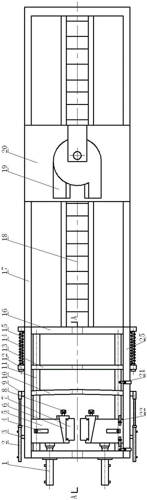
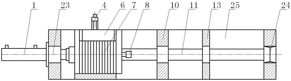
[0017] A tube extubation machine with a feeding device, including a fuselage 17, a machine head 16, a feeding device, a trolley 20, and a chain 18, the chain is installed horizontally on the top of the fuselage, and is slidably installed between the two sides of the fuselage on both sides of the chain A trolley is equipped with clamps, a machine head is installed on one side of the fuselage, and a feeding device is installed in the machine head.

[0018] The feeding device includes a mounting frame 25, a pushing mechanism, a push plate 10 and a straightening plate 13. The mounting frame is a rectangular frame, and two optical axes 11 are symmetrically fixed up and down between the left and right side ...


PUM


Abstract

The invention relates to a tube drawing bench with a feeding device. The tube drawing bench comprises a bench body, a bench head, the feeding device, a trolley and a chain. The chain is installed at the top of the bench body. The trolley is installed between two side plates, at the two sides of the chain, of the bench body in a sliding mode. A clamp is installed on the trolley. The bench head is installed on one side of the bench body. The feeding device is installed in the bench head, and comprises an installation frame, a pushing mechanism, a pushing plate and a straightening plate. The installation frame is a rectangular frame. Two plain shafts are fixedly arranged between a left side plate and a right side plate of the installation frame in a vertically-symmetric mode. The pushing mechanism, the pushing plate and the straightening plate are sequentially installed between the two plain shafts at intervals in a sliding mode. Feeding holes are coaxially formed in the centers of the pushing plate, the straightening plate and the left side plate and the right side plate of the installation frame. An annular tool is coaxially installed in the feeding hole of the right side plate of the installation frame. The tube drawing bench is used for ejecting the heads of bars out of the annular tool through the pushing mechanism, so that the heads of the bars are clamped by the clamp of the trolley; the drawing-down procedure of the heads of the bars is omitted, labor is saved, and the working efficiency is improved.

Description

technical field [0001] The invention belongs to the field of extubation machines, in particular to an extubation machine with a feeding device. Background technique [0002] After long-term storage of copper rods, oxide scales will appear on the surface, affecting sales. In order to remove the oxide scales, a tube exfoliator is usually used. During the drawing process, the copper rods are stripped of the oxide scales by the ring cutter at the head of the tube extubation machine. The traditional extubation machine does not have a feeding device. Before installing the copper rod, a head with a smaller diameter needs to be cut out at the starting end of the copper rod. Clamping, the trolley travels on guide rails, thereby pulling the bar out of the ring cutter. The disadvantage of this method is obvious. On the one hand, a small section of each copper rod is wasted. On the other hand, cutting the head of the copper rod is equivalent to adding a process, which is time-consuming...

Claims


Application Information

Patent Timeline
Patent Type & Authority Applications(China)
IPC IPC(8): B21C1/22B21C1/32
CPCB21C1/22B21C1/32
Inventor 沈东
Owner TIANJIN DONGQI VALVE MFG CO LTD
Why Eureka
Try Eureka