A steady flow device for continuous casting crystallizer

A technology of continuous casting crystallizers and flow stabilization devices, which is applied in the field of flow stabilization devices, can solve problems such as the failure of the optimized flow field effect, and achieve the effects of uniform and reasonable speed distribution, long working hours, and reduced inclusions

Active Publication Date: 2017-11-10
重庆泽云科技有限公司
View PDF7 Cites 0 Cited by
  • Summary
  • Abstract
  • Description
  • Claims
  • Application Information

AI Technical Summary

Problems solved by technology

However, after a period of pouring in the submerged nozzle, the inclusions in the molten steel will form nodules inside the nozzle. At this time, the internal structure of the nozzle will no longer exist, resulting in the failure of the effect of optimizing the flow field.

Method used


Image

  • A steady flow device for continuous casting crystallizer
  • A steady flow device for continuous casting crystallizer
  • A steady flow device for continuous casting crystallizer

Examples


Embodiment 1

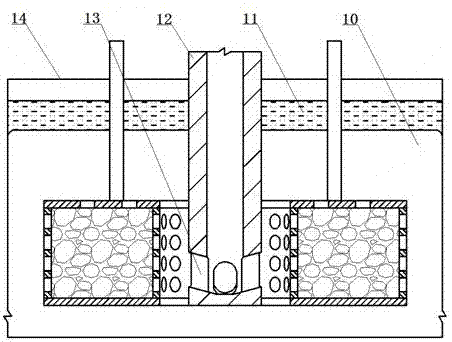
[0028] The utility model relates to a constant flow device for a continuous casting crystallizer. This example image 3 As shown, the continuous casting mold 14 is used to produce 600mm round billet. The outer diameter of the four-hole submerged nozzle 12 used in conjunction with the continuous casting crystallizer 14 is 100 mm, and the immersion depth of the four-hole submerged nozzle 12 is 150 to 200 mm during the pouring process.

[0029] Such as image 3 As shown, the present embodiment is immersed in molten steel 10 at a height of 150-200 mm below the meniscus at the level of the outlet hole 13 of the four-hole submerged nozzle 12 in the continuous casting crystallizer 14. The surface of molten steel 10 is covered with mold slag 11 .

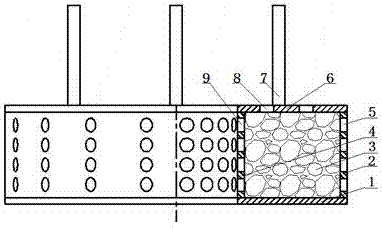
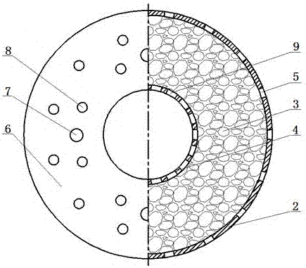
[0030] This example figure 1 with figure 2 As shown, the flow stabilization device is composed of a base 1 , an outer casing 2 , an inner casing 4 , a cover plate 6 , a lifting rod 7 and a filling material 3 . The lower end of the ou...

Embodiment 2

[0039]The utility model relates to a constant flow device for a continuous casting crystallizer. Present embodiment except following technical parameters, all the other are with embodiment 1:

[0040] This embodiment is used to produce a continuous casting crystallizer of 150×150mm billet. The outer diameter of the double-hole submerged nozzle used in conjunction with the continuous casting crystallizer is 20mm, and the immersion depth of the double-hole submerged nozzle is 100-150mm during the pouring process. in:

[0041] The outer sleeve 2 is square tubular, and the inner diameter of the inner sleeve 4 is 0.2 to 0.5 times the diagonal of the square tube;

[0042] The thickness of the base 1, the thickness of the cover plate 6, the wall thickness of the inner casing 4 and the outer casing 2 are the same, all of which are 10-30mm;

[0043] The height of the outer casing 2 is 100-200mm;

[0044] The diameters of the outer diversion hole 5, the inner diversion hole 9 and th...


PUM

PropertyMeasurementUnit
heightaaaaaaaaaa
heightaaaaaaaaaa

Abstract

The invention relates to a flow stabilizing device for a continuous casting mold. According to the technical scheme, lower ends of an outer sleeve pipe (2) and an inner sleeve pipe (4) are coaxially fixed on a base (1); upper ends of the outer sleeve pipe (2) and the inner sleeve pipe (4) are coaxially fixed with a cover plate (6); an annular hollow cavity surrounded by the base (1), the outer sleeve pipe (2), the inner sleeve pipe (4) and the cover plate (6) is internally provided with a filling material (3); outer flow guide holes (5) are uniformly opened in the wall of the outer sleeve pipe (2); inner flow guide holes (9) are uniformly opened in the wall of the inner sleeve pipe (4); top flow guide holes (8) are uniformly opened in the cover plate (6); and the total area of the inner flow guide holes (9) is 1 to 1.2 times the sum of the total area of the outer flow guide holes (5) and the total area of the top flow guide holes (8). The flow stabilizing device for the continuous casting mold has the advantages that the structure is simple, replacement is convenient, the cost is low, a steel liquid flow field inside the mold can be improved, slag entrapment phenomena on a steel slag interface is reduced, and inclusions in the steel liquid are captured.

Description

technical field [0001] The invention belongs to the technical field of flow stabilization devices. In particular, it relates to a flow stabilization device for continuous casting crystallizers. Background technique [0002] The mold is an important part in the continuous casting process, and its internal flow field distribution, free liquid surface fluctuation and primary slab shell growth directly affect the surface quality and internal quality of the slab. This is because the flow field of the molten steel directly affects the position of the vortex center of the molten steel in the mold and the impact depth of the jet, and these factors affect the floating of inclusions and air bubbles; the fluctuation of the free liquid surface will affect the mold The melting and inclusion of the inner mold slag; and whether the growth of the primary slab shell can reach a certain thickness will affect the shape of the mold exit slab shell and the thickness of the solidified slab shell...

Claims


Application Information

Patent Timeline
Patent Type & Authority Patents(China)
IPC IPC(8): B22D11/10
Inventor 金焱金业磊肖锋冯学武常正昇李洋袁辉罗霄叶琛程常桂
Owner 重庆泽云科技有限公司
Why Eureka
Try Eureka