Twist beam suspension

A technology of torsion beams and suspensions, applied in suspensions, elastic suspensions, transportation and packaging, etc., can solve the problems of cracking at the joints of installation bushes and beams and longitudinal beams, excessive load transfer of the body, and affecting handling performance, etc. Achieve the effect of reducing the risk of structural cracking, improving handling performance, and improving handling performance

Inactive Publication Date: 2015-10-28
ANHUI TECHN COLLEGE OF MECHANICAL & ELECTRICAL ENG
View PDF4 Cites 1 Cited by
  • Summary
  • Abstract
  • Description
  • Claims
  • Application Information

AI Technical Summary

Problems solved by technology

Such a structure has disadvantages. First, it simply relies on the connection point between the longitudinal beam and the body to bear the lateral force, resulting in excessive local loads, and cracks often occur at the joints of the longitudinal beam, the installation bushing, and the lap of the beam and longitudinal beam; The second is that the body load is transferred too much, which affects the handling performance

Method used


Image

  • Twist beam suspension
  • Twist beam suspension

Examples


Embodiment Construction

[0019] See attached picture:

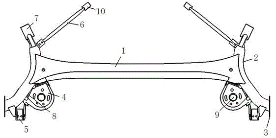
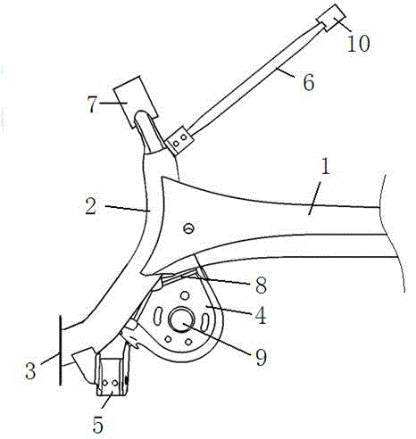
[0020] The torsion beam suspension includes a beam 1, and the two ends of the beam 1 are symmetrically provided with a longitudinal beam 2, and the lower end of the longitudinal beam 2 is connected with a longitudinal hub plate 3 for installing wheels; the connection between the longitudinal beam 2 and the beam 1 The lower end is fixedly equipped with a spring seat 4, and a shock absorber mounting bracket 5 is installed on the longitudinal beam 2 on the lower side of the spring seat 4, and the lower side of the outer wall of the spring seat 4 is also welded and fixed with the upper side of the outer wall of the shock absorber bracket 5; A reinforcement bar 6 is installed on the inner sidewall of the upper end of the 2.

[0021] The beam 1 is usually stamped from thick sheet metal, and the thickness is generally 5mm~7mm. The upward or downward opening shape of the beam 1 can be U-shaped or V-shaped, that is, the middle part protrudes outward into ...


PUM


Abstract

The invention discloses a twist beam suspension. The twist beam suspension comprises a cross beam, wherein longitudinal beams are symmetrically arranged at the two ends of the cross beam; the lower ends of the longitudinal beams are connected with longitudinal hub plates for mounting wheels; spring seats are fixedly mounted at the lower ends of the longitudinal beams connected with the cross beam; shock absorber mounting brackets are mounted on the longitudinal beams on the lower sides of the spring seats; the lower sides of the outer walls of the spring seats are also fixed together with the upper sides of the outer walls of the shock absorber mounting brackets through welding; and reinforcing rods are mounted on the inner side walls of the upper ends of the longitudinal beams. Through the adoption of the reinforcing rod structures, partial loads on bushings at the front ends of the longitudinal beams are shared by the reinforcing rods under conditions that a vehicle is turning, passing a pit and so on when the load is born on the suspension; therefore, the load of the suspension are shared at a plurality of points so that structural cracking risks at the mounting points of the bushings at the front sections of the longitudinal beams of the twist beam suspension are reduced. As the cross beam, the longitudinal beams, the spring seats, the shock absorber mounting brackets, the reinforcing rods, the hub plates and so on are reasonably assembled together, the maneuvering performance of the whole vehicle is effectively improved and the reliability and maneuverability of a chassis are enhanced.

Description

technical field [0001] The invention relates to the field of automobile manufacturing, in particular to a torsion beam suspension. Background technique [0002] Automobile suspension is an important part of the vehicle, it is the connecting force transmission device between the body and the wheels, and it is also an important factor affecting the driving safety, comfort and handling of the vehicle. The torsion beam suspension has the advantages of simple structure, low manufacturing cost, and good cost performance, and is used as the rear suspension of many models. During driving, when the vehicle is turning, the suspension system bears a large lateral force. [0003] In the existing torsion beam suspension system, the lateral force is borne by the connection point between the torsion beam longitudinal beam and the vehicle body. Such a structure has disadvantages. First, it simply relies on the connection point between the longitudinal beam and the body to bear the lateral...

Claims


Application Information

Patent Timeline
Patent Type & Authority Applications(China)
IPC IPC(8): B60G11/20
Inventor 李琤阮砚珏姜能惠
Owner ANHUI TECHN COLLEGE OF MECHANICAL & ELECTRICAL ENG
Why Eureka
Try Eureka