
Splitting-type thin oil lubricating bearing seat

A technology of thin oil lubrication and bearing seat, which is applied in the direction of bearing components, shafts and bearings, engine lubrication, etc., can solve problems such as blackened grease, overflow, environmental pollution, etc., achieve limit speed increase, reduce bearing temperature, increase The effect of service life

Active Publication Date: 2015-10-28
JIANGSU HENGLIANG CENTRIFUGE MFG
View PDF7 Cites 7 Cited by
  • Summary
  • Abstract
  • Description
  • Claims
  • Application Information

AI Technical Summary

Problems solved by technology

[0002] The national standard split bearing seat is a type commonly used in decanter centrifuges. It is expected that the existing split bearing seat will be used as the main bearing seat of the drum of the centrifuge, and the rotating speed of the drum is 4500 rpm ~2000 rpm, but according to the current market situation, its speed cannot meet the production needs of users. The national standard split bearing seat is lubricated with grease, and the limit speed of the bearing is limited. For example, in the LW450 centrifuge, the main bearing The deep groove ball bearing seat 6222 used has a limit speed of 2800 rpm for grease lubrication and 3400 rpm for thin oil lubrication. Grease is not allowed when the CMC material is separated. In the case of explosion-proof requirements, all Grease is not allowed; grease is used to lubricate manually with an oil cup and timed pressurized lubrication, blackened grease will overflow after long-term use, polluting the environment

Method used


Image

  • Splitting-type thin oil lubricating bearing seat

Examples


Embodiment Construction

[0014] Embodiments of the present invention are described in detail below, examples of which are shown in the drawings, wherein the same or similar reference numerals designate the same or similar elements or elements having the same or similar functions throughout. The embodiments described below by referring to the figures are exemplary only for explaining the present invention and should not be construed as limiting the present invention. On the contrary, the embodiments of the present invention include all changes, modifications and equivalents coming within the spirit and scope of the appended claims.

[0015] In the description of the present invention, it should be understood that the terms "first", "second" and so on are used for descriptive purposes only, and cannot be interpreted as indicating or implying relative importance. In the description of the present invention, it should be noted that unless otherwise specified and limited, the terms "connected" and "connect...


PUM


Abstract

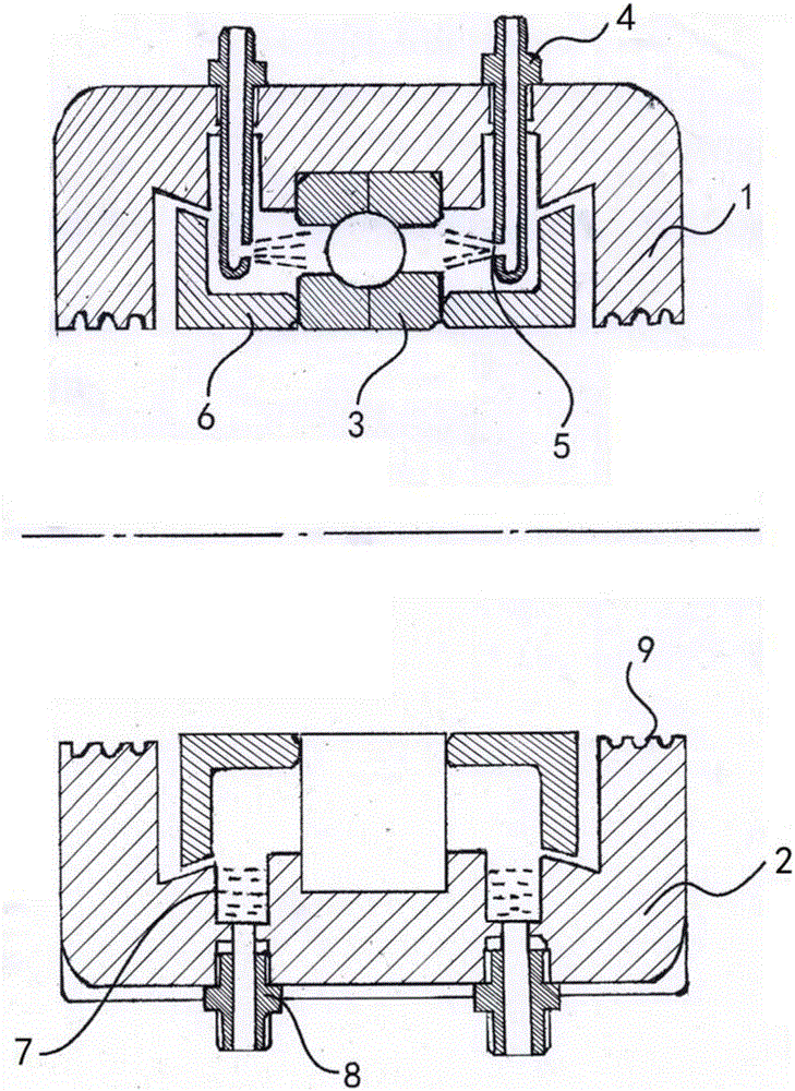
The invention provides a splitting-type thin oil lubricating bearing seat. The splitting-type thin oil lubricating bearing seat comprises an upper cover and a base. After the upper cover is fixed to the base in a jointing mode, an annular groove used for installing of a bearing is formed. The outer ring of the bearing is arranged in the annular groove in an embedded mode. The portions, arranged on the two sides of the annular groove, on the top of the upper cover are axially provided with radial through holes respectively. An oil nozzle is arranged in each radial through hole. The portions, close to the lower ends, on the sides of the oil nozzles are provided with nozzle holes which face the bearing. According to the splitting-type thin oil lubricating bearing seat, oil can be supplied continuously through a hydraulic station by lubricating oil, it is not needed that oil supplying is carried out by manpower in a timing mode, the lubricating oil is returned back to an oil tank of the hydraulic station for being recycled, oil retainers are utilized, it is guaranteed that the lubricating oil cannot be leaked, and the leakage phenomenon does not exist. Meanwhile, a part of ball friction heat is taken away by the lubricating oil, the temperature of the bearing seat is far lower than the temperature of a lubricating grease lubricating bearing seat, the limit speed of the bearing can be improved by 20%, the temperature of the bearing is lowered, the service life of the bearing is prolonged, and maintaining of the bearing is lowered.

Description

technical field [0001] The invention relates to the technical field of bearing seats, in particular to a split thin oil lubricated bearing seat. Background technique [0002] The national standard split bearing seat is a type commonly used in decanter centrifuges. It is expected that the existing split bearing seat will be used as the main bearing seat of the drum of the centrifuge, and the rotating speed of the drum is 4500 rpm ~2000 rpm, but according to the current market situation, its speed cannot meet the production needs of users. The national standard split bearing seat is lubricated with grease, and the limit speed of the bearing is limited. For example, in the LW450 centrifuge, the main bearing The deep groove ball bearing seat 6222 used has a limit speed of 2800 rpm for grease lubrication and 3400 rpm for thin oil lubrication. Grease is not allowed when the CMC material is separated. In the case of explosion-proof requirements, all Grease is not allowed; grea...

Claims


Application Information

Patent Timeline
Patent Type & Authority Applications(China)
IPC IPC(8): F16C35/04F16N1/00
Inventor 陈嵘谭芳媛于网华蒋丽影
Owner JIANGSU HENGLIANG CENTRIFUGE MFG
Learn More