Al technical title is built by PatSnap Al team. It summarizes the technical point description of the patent document.
A closing and emergency technology, applied in the direction of sliding valves, valve details, valve devices, etc., can solve the problems of affecting the stability of the sealed valve stem, slow opening and closing speed, increasing the overall weight of the gate valve, etc., to achieve rapid opening and closing, The effect of fast transmission speed and prolonged service life
Inactive Publication Date: 2015-10-28
FANGZHENG VALVE GRP WENZHOU MACHINERY MFG
View PDF9 Cites 0 Cited by
Summary
Abstract
Description
Claims
Application Information
AI Technical Summary
This helps you quickly interpret patents by identifying the three key elements:
Problems solved by technology
Method used
Benefits of technology
Problems solved by technology
[0003] The gate valve is a widely used control valve. The opening and closing of the existing gate valves are realized by screwing the valve stem to drive the gate plate to rise and fall. Therefore, the speed of opening and closing is very slow. For some occasions that require the valve to be opened or closed quickly, especially the occasions involving safety, the existing threaded screw-opening gate valve is difficult to adapt and meet the use requirements.
[0004] And usually the connection between the valve stem and the valve body is filled with packing to achieve sealing. Some parts of the valve stem are exposed to the outside, and are prone to failure and damage in some harsh environments. , it is easy to drive the packing during the operation of the valve stem, and sometimes the packing will be taken out, which will affect the sealing and the stability of the valve stem. Since the packing will be lost, multi-layer packing layers are usually set to ensure long-term maintenance. normal operation, thus greatly increasing the overall weight of the gate valve
Method used
Image
Click on the blue label to locate the original text in one second.
Reading with bidirectional positioning of images and text.
Examples
Embodiment Construction
[0017] refer to Figure 1 to Figure 2 The embodiment of the emergency opening and closing gate valve of the present invention will be further described.
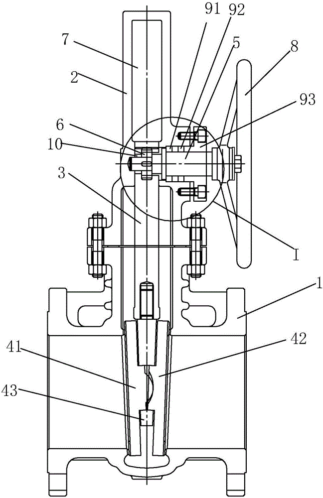
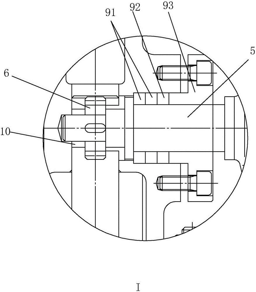
[0018] An emergency opening and closing gate valve, including a valve body 1, a valve cover 2 and a valve stem 3, the end of the valve stem 3 located in the valve body 1 is provided with a valve plate for opening and closing, and the valve stem 3 is provided with an operating valve perpendicular to it. The shaft 5 and the key on the operating shaft 5 are connected with the gear 6, the valve stem 3 is provided with a rack meshing with the gear 6, and the valve cover 2 is provided with a channel 7 for the valve stem 3 to rise and fall, and the valve cover 2 wraps and seals the entire valve stem 3. The end of the operating shaft 5 located outside the valve cover 2 is provided with a hand wheel 8 .
[0019] The opening and closing method of the valve plate abandons the traditional way of screwing the valve stem 3, and uses the ...
PUM
Abstract
The invention discloses an emergent opening/closing gate valve. The emergent opening/closing gate valve is characterized by comprising a valve body, a valve cover and a valve rod, wherein one end, positioned in the valve body, of the valve rod is provided with a valve plate for opening/closing; the valve rod is provided with an operation shaft perpendicular to the valve rod; the operation shaft is connected with a gear through a key; the valve rod is provided with a rack engaged with the gear; a channel for lifting the valve rod is formed in the valve cover; the whole valve rod is wrapped by the valve cover; an opening/closing mode of the valve plate abandons a traditional mode of spirally screwing the valve rod; a gear-rack transmission mode is adopted; the operation shaft rotates; then, the valve rod is driven to vertically lift by a small gear and the rack on the valve rod to realize the opening/closing; the transmission structure is large in transmission torque and quick in transmission speed, can realize quick opening/closing of the valve, is simpler, labor-saved and quicker in operation, and is suitable for specific places; and the whole valve rod is wrapped and sealed by the valve cover to prevent from easily being damaged under bad environments, so that the service life is prolonged.
Description
technical field [0001] The invention relates to the field of valves, more specifically, it relates to an emergency opening and closing gate valve. Background technique [0002] Valves are the control components in the fluid conveying system. They have the functions of cut-off, adjustment, flow diversion, reverse flow prevention, pressure stabilization, flow diversion or overflow pressure relief. Valves, ball valves and butterfly valves, etc., are widely used in natural gas long-distance pipelines, metallurgy, hydropower, thermal power, urban water supply and drainage, farmland drainage and irrigation and other industries, and are suitable for natural gas, coal gas, steam, air, water, etc. In changing the pipeline system, it is used to cut off or connect the medium. [0003] The gate valve is a widely used control valve. The opening and closing of the existing gate valves are realized by screwing the valve stem to drive the gate plate to rise and fall. Therefore, the speed ...
Claims
Application Information
Patent Timeline
Application Date:The date an application was filed.
Publication Date:The date a patent or application was officially published.
First Publication Date:The earliest publication date of a patent with the same application number.
Issue Date:Publication date of the patent grant document.
PCT Entry Date:The Entry date of PCT National Phase.
Estimated Expiry Date:The statutory expiry date of a patent right according to the Patent Law, and it is the longest term of protection that the patent right can achieve without the termination of the patent right due to other reasons(Term extension factor has been taken into account ).
Invalid Date:Actual expiry date is based on effective date or publication date of legal transaction data of invalid patent.