
Fiber Bragg Grating-Based Sound Sensor

A technology of sound sensor and optical fiber grating, which is applied in the direction of instruments, measuring ultrasonic/sonic/infrasonic waves, measuring devices, etc. It can solve the problems that the system is easily affected by the ambient temperature, the sound monitoring range is small, and the sensitivity is low, so as to facilitate network monitoring , Increase the sound monitoring range, improve the effect of sensitivity

Active Publication Date: 2017-12-29
WUHAN WUTOS
View PDF5 Cites 0 Cited by
  • Summary
  • Abstract
  • Description
  • Claims
  • Application Information

AI Technical Summary

Problems solved by technology

[0003]1. It is extremely susceptible to interference from other strong and complex electromagnetic signals in the environment, resulting in sensor failure;
[0004]2. The electromagnetic radiation signal generated during the self-sensing process is also easily captured and stolen by other devices;
[0005]3. Without adding relay devices, the signal transmission distance is limited and it is not easy to form a network;
[0006]4. In some flammable and explosive occasions, live devices are dangerous and their use is limited
[0007] In addition, there are also a few sound sensors based on optical principles, such as the "Sound Vibration Acquisition Device Based on Fiber Bragg Grating" with the patent No. 101718580A and the "Fiber Bragg Grating Sound Sensor for Mine" with the patent No. Disadvantages such as small size, low sensitivity, and the whole system is easily affected by ambient temperature

Method used


Image

  • Fiber Bragg Grating-Based Sound Sensor
  • Fiber Bragg Grating-Based Sound Sensor
  • Fiber Bragg Grating-Based Sound Sensor

Examples


Embodiment Construction

[0023] In order to make the object, technical solution and advantages of the present invention clearer, the present invention will be further described in detail below in conjunction with the accompanying drawings and embodiments. It should be understood that the specific embodiments described here are only used to explain the present invention, not to limit the present invention.

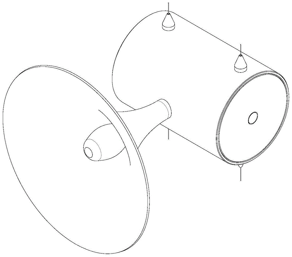
[0024] In order not to introduce electrical signals, improve the sensitivity of the sensor, increase the sound monitoring range, make the sound not affected by the ambient temperature, and facilitate network monitoring, such as figure 1 As shown, the present invention provides an acoustic sensor based on fiber grating sensing, which can meet the above requirements, especially in terms of improving sensitivity and solving the influence of ambient temperature.

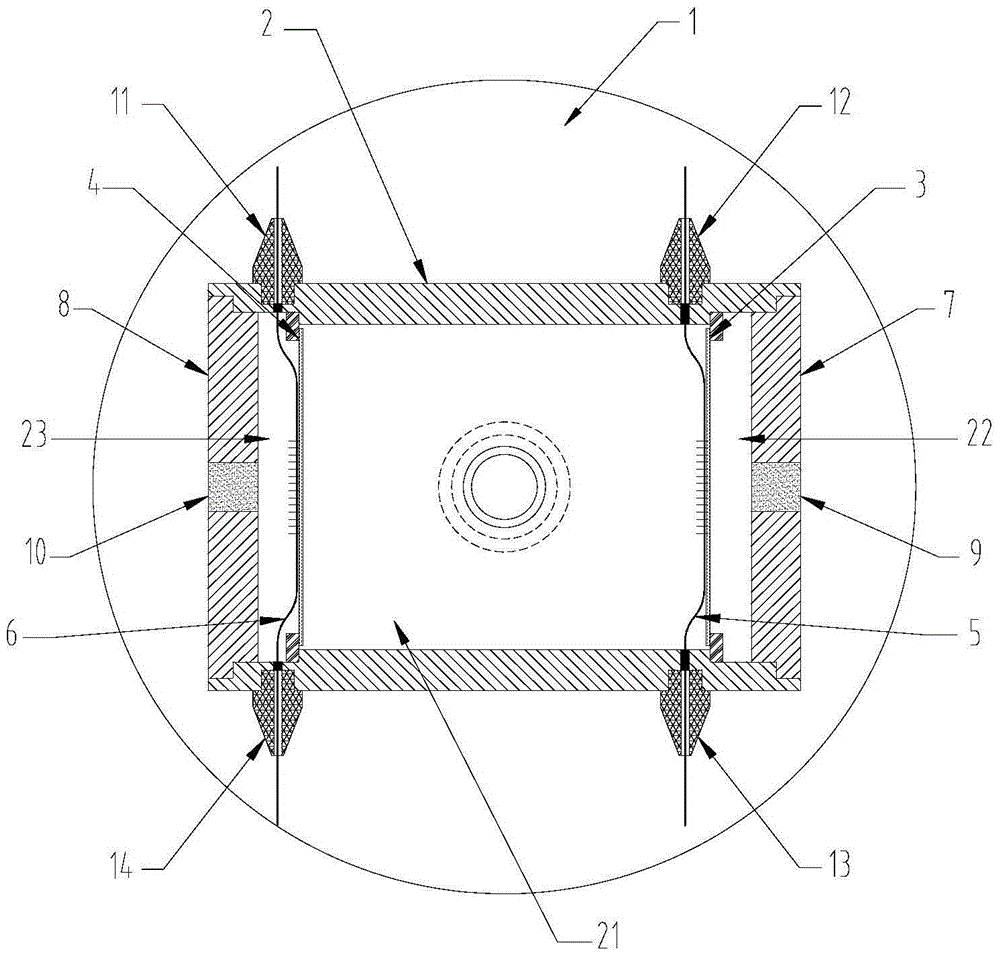
[0025] Such as figure 2 As shown, the fiber grating-based acoustic sensor of the embodiment of the present invention includes a sound coll...


PUM


Abstract

The invention discloses a sound sensor based on optical fiber grating, which includes a sound collecting device and a sound amplifying device, the two are connected through a waterproof and dustproof channel, and two wide-frequency sound diaphragms are arranged in the sound amplifying device, and the sound is amplified A resonant cavity is formed in the device, and a fiber grating is arranged on the wide frequency domain sound diaphragm, and the fiber grating is connected with an external signal demodulator. The invention can improve the sensitivity of the sensor, increase the range of sound monitoring, and facilitate the monitoring of a plurality of sensors in a network.

Description

technical field [0001] The invention relates to an acoustic sensor, in particular to an acoustic sensor based on a fiber grating. Background technique [0002] At present, most of the sound acquisition sensors that are widely used are based on electrical methods, such as moving coil and capacitive sound sensors, which convert sound signals into electrical signals such as current and voltage for processing. The sensors that adopt this method are as follows Disadvantages in several aspects: [0003] 1. It is extremely susceptible to interference from other strong and complex electromagnetic signals in the environment, resulting in sensor failure; [0004] 2. The electromagnetic radiation signal generated during the self-sensing process is also easily captured and stolen by other devices; [0005] 3. Without adding a relay device, the signal transmission distance is limited and it is not easy to form a network; [0006] 4. In some flammable and explosive occasions, live devi...

Claims


Application Information

Patent Timeline
Patent Type & Authority Patents(China)
IPC IPC(8): G01H9/00
Inventor 何光辉董雷王丹印新达
Owner WUHAN WUTOS
Learn More