Pressure sensing method and sensor probe utilizing method

A sensor probe and sensing method technology, applied in the direction of fluid pressure measurement using optical methods, can solve the problems of cumbersome pressure measurement and calculation, poor sensor performance stability, low measurement accuracy, etc., and achieve adaptability and interchangeability progress. , strong practicability, calculated the effect of simple measurement

Inactive Publication Date: 2015-10-28
GUIZHOU UNIV
View PDF4 Cites 15 Cited by
  • Summary
  • Abstract
  • Description
  • Claims
  • Application Information

AI Technical Summary

Problems solved by technology

[0003] The purpose of the present invention is to provide a pressure sensing method and a sensor probe using the method, so as to solve the problem that the measurement and calculation of the pressure by the existing elastic diaphragm sensor are complicated, the measurement accuracy is not high, and the performance of the existing sensor is stable. Poor performance, short service life, etc.

Method used


Image

  • Pressure sensing method and sensor probe utilizing method

Examples


Embodiment

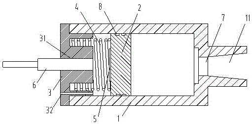
[0015] refer to figure 1 , this embodiment provides a differential pressure sensing method, which uses the pressure generated by the fluid to impact one side of a sliding piston 2, the piston 2 slides, and the other side of the piston 2 is provided with a spring 4 to limit the movement of the piston 2 At the same time, the other side of the piston 2 is also provided with a reflector 5, and irradiates the reflector 5 with the incident optical fiber in the fiber optic probe 6, and receives the reflected light with the receiving optical fiber in the fiber optic probe 6. After the piston 2 moves, the fiber optic probe When the distance between 6 and the mirror 5 changes, the reflected light changes accordingly, and the pressure caused by the detection fluid on the piston is judged by detecting the change of the output light intensity of the receiving optical fiber.

[0016] The sensor probe using the above-mentioned pressure sensing method includes a shell 1 with a cylindrical str...


PUM


Abstract

The invention provides a pressure sensing method and a sensor probe utilizing the method. The pressure sensing method is characterized in that one surface of a piston arranged in a sliding manner is impacted by a pressure generated by a fluid, the piston slides, the other surface of the piston is provided with a reflective mirror, incident optical fibers in an optical fiber probe irradiate the reflective mirror, and receiving optical fibers in the optical fiber probe receive reflective light; and after the piston moves, the distance between the optical fiber probe and the reflective mirror changes, the reflective light also changes, the pressure change of an elastic membrane caused by the fluid is judged and detected by detecting the change of output light intensity of the receiving optical fibers, and the other surface of the piston is provided with a spring to limit the moving amount of the piston. The pressure sensing method and the sensor probe utilizing the method solve the problems that pressure measurement and calculation by using an existing elastic membrane sensor is relatively tedious, the measuring precision is not high, the existing sensor is relatively poor in stability, and the usage lifetime is relatively short. The invention belongs to the field of pressure detection.

Description

technical field [0001] The invention relates to a sensing method and a sensor probe structure, belonging to the technical field of optical fiber sensing. Background technique [0002] Existing optical fiber pressure sensors for measuring fluid pressure all use elastic diaphragms as pressure sensing devices. However, the fluid pressure contacted by each part of the elastic diaphragm is generally unevenly distributed, and there will be a certain pressure difference more or less, making the elastic diaphragm The uneven deformation of each part of the film affects the measurement accuracy of the sensor. The elastic diaphragm deforms in an arc shape when deformed. The measurement and calculation of the pressure that causes the arc deformation is cumbersome. At the same time, the elastic diaphragm is easily disturbed by the outside world. Or damaged, the performance of the sensor probe is unstable, and the service life is short. Contents of the invention [0003] The purpose of...

Claims


Application Information

Patent Timeline
Patent Type & Authority Applications(China)
IPC IPC(8): G01L11/02
Inventor 胡浩钟丽琼
Owner GUIZHOU UNIV
Why Eureka
Try Eureka