Device for tensile test of metal material under function of current

A metal material, tensile test technology, applied in the direction of measuring devices, analysis materials, instruments, etc., to achieve the effect of reasonable design, convenient use, and stable current

Inactive Publication Date: 2015-10-28
HAIAN GASOLINEEUM SCI RES INSTR
View PDF7 Cites 9 Cited by
  • Summary
  • Abstract
  • Description
  • Claims
  • Application Information

AI Technical Summary

Problems solved by technology

[0003] At present, there is no fixture that can be used for the tensile test of metal materials under the action of electric current. For this reason, this application has made the following technical proposal

Method used


Image

  • Device for tensile test of metal material under function of current
  • Device for tensile test of metal material under function of current

Examples


Embodiment Construction

[0013] The present invention will be described in further detail below in conjunction with the accompanying drawings.

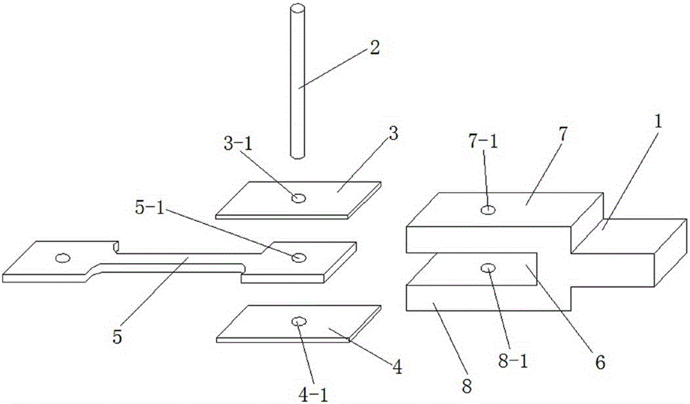
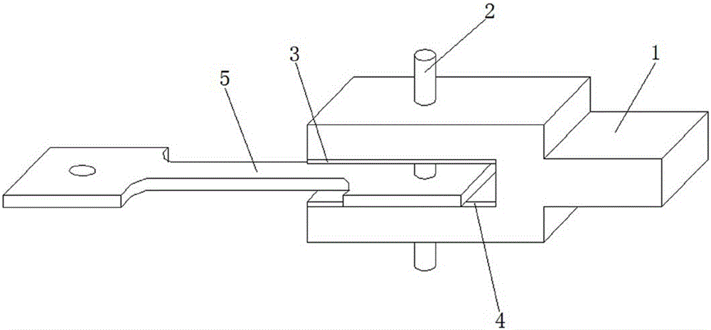
[0014] like figure 1 As shown, a tensile test device for metal materials under the action of electric current includes a clamp and a tensile sample 5. The clamp includes a clamping seat 1, an insulating ceramic rod 2, an insulating upper backing plate 3, and an insulating lower pad plate 4, one end of the clamping seat 1 is provided with a U-shaped groove 6, and the insulating upper backing plate 3, the tensile sample 5 and the insulating lower backing plate 4 are sequentially arranged in the U-shaped groove 6 from top to bottom Inside, the insulating ceramic rod 2 runs through the clamping seat 1 , the insulating upper backing plate 3 , the tensile sample 5 and the insulating lower backing plate 4 .

[0015] like figure 1 As shown, the upper side plate 7 of the U-shaped groove 6 is provided with a first round hole 7-1, and the lower side plate 8 of the U-s...


PUM


Abstract

The invention relates to the technical field of mechanical property testing devices, and particularly relates to a device for a tensile test of a metal material under the function of current. The device comprises a fixture and a tensile sample, wherein the fixture comprises a clamping seat, an insulating ceramic bar, an insulating upper padding plate and an insulating lower padding plate, one end of the clamping seat is provided with a U-shaped groove, the insulating upper padding plate, the tensile sample and the insulating lower padding plate are sequentially arranged in the U-shaped groove from top to bottom, and the insulating ceramic bar penetrates through the clamping seat, the insulating upper padding plate, the tensile sample and the insulating lower padding plate. By adopting the structure, the fixture of a tensile testing machine is not needed to be modified, the mechanical property of the metal material under the function of current can be measured through the tensile test by only clamping the fixture onto the tensile testing machine and utilizing the tensile sample provided by the invention, and meanwhile, the fixture can ensure that the tensile sample is insulated from tensile equipment.

Description

technical field [0001] The invention relates to the technical field of mechanical performance testing devices, in particular to a tensile testing device for metal materials under the action of electric current. Background technique [0002] Tensile test has always been the best method for determining the mechanical properties of materials. The tensile test can obtain the yield strength, tensile strength, elongation and area reduction of the material. These parameters play a decisive role in the use of the material, but With the gradual specialization of the use environment of certain materials, the performance changes of these materials in special environments have been paid more and more attention. For example, in the field of electronic packaging, solder alloy solder joints not only play the role of mechanical connection, but also play the role of electrical connection, and receive the dual effects of force and current during work. Therefore, the solder alloy solder joints...

Claims


Application Information

Patent Timeline
Patent Type & Authority Applications(China)
IPC IPC(8): G01N3/04
Inventor 金雪松王永明
Owner HAIAN GASOLINEEUM SCI RES INSTR
Why Eureka
Try Eureka