Method, system and device for measuring channel state information

A technology for channel state information and user equipment, applied in transmission systems, radio transmission systems, diversity/multi-antenna systems, etc. Effect

Active Publication Date: 2015-10-28
DATANG MOBILE COMM EQUIP CO LTD
View PDF3 Cites 38 Cited by
  • Summary
  • Abstract
  • Description
  • Claims
  • Application Information

AI Technical Summary

Problems solved by technology

[0006] The present invention provides a method, system and equipment for channel state information measurement, which are used to solve the problem existing in the prior art that under the premise of giving full play to the performance advantages of Massive MIMO, the current mechanism based on downlink reference signal measurement and feedback CSI will bring Significant time-frequency resource overhead issues

Method used


Image

  • Method, system and device for measuring channel state information
  • Method, system and device for measuring channel state information
  • Method, system and device for measuring channel state information

Examples


Embodiment 7

[0157] Such as Figure 7 As shown, the method for measuring channel state information in Embodiment 7 of the present invention includes:

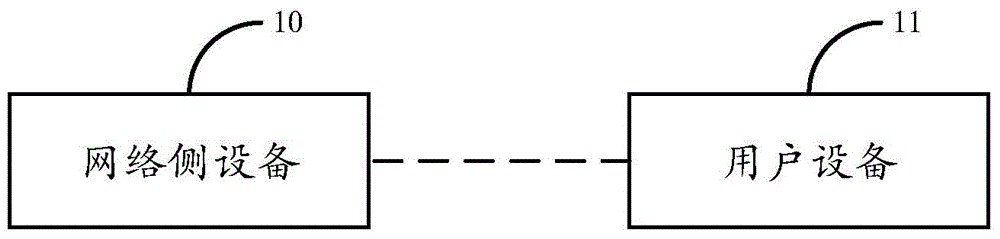
[0158] Step 701, the network side device sends a set of beamformed reference signals to the user equipment, so that the user equipment can measure the reference signals, wherein each reference signal in the set of reference signals corresponds to a space in a sector;

[0159] Step 702, the network side device judges whether to adjust the shaping mode of the reference signal according to the information fed back by the user equipment.

[0160] Preferably, each reference signal in a sector corresponds to a different channel state information measurement reference signal CSI-RS configuration and / or a different CSI-RS port.

[0161] Preferably, each reference signal in a sector corresponds to a different identifier.

[0162] Preferably, the network side device judges whether to adjust the shaping mode of the reference signal according to the ...

Embodiment 8

[0175] Such as Figure 8 As shown, the eight-channel state information measurement method of the embodiment of the present invention includes:

[0176] Step 801, the user equipment measures a set of beamformed reference signals received from the network side equipment, where each reference signal in a set of reference signals corresponds to a space in a sector;

[0177] Step 802, the user equipment feeds back information to the network side device according to the measurement result, so that the network side device judges whether to adjust the shaping mode of the reference signal according to the fed back information.

[0178] Preferably, the information fed back by the user equipment to the network side equipment according to the measurement results includes:

[0179] The user equipment feeds back the identification of the reference signal for measurement and the corresponding quality information to the network side equipment.

[0180] Preferably, the information fed back b...


PUM


Abstract

Embodiments of the present invention relate to wireless communication technical field, and particularly to a method, system and device for measuring channel state information, used for solving the existing problem in the prior art that on the premise of making full use of the performance advantage of Massive MIMO, the current CSI measurement and feedback mechanism based on downlink reference signal would result in significant time-frequency resource overhead. The method for measuring channel state information provided in the embodiments of the present invention comprises that: a network side device transmits a group of reference signals which have been beam-formed to a user equipment in order that the user equipment can measure the reference signals, wherein each reference signal of the group of reference signals corresponds to a space in a section; and the network side device judges whether to adjust the forming manner of the reference signal on the basis of the information fed back by the user equipment. By applying the solution of the embodiments of the present invention, on the premise of ensuring the Massive MIMO performance advantage, the overhead resulting from the downlink reference signal measurement and feedback can be reduced.

Description

technical field [0001] The present invention relates to the technical field of wireless communication, in particular to a method, system and equipment for measuring channel state information. Background technique [0002] In view of the important role of MIMO (Multiple Input Multiple Output) technology in improving peak rate and system spectrum utilization, LTE (Long Term Evolution, long-term evolution) / LTE-A (LTE-Advanced, long-term evolution upgrade) etc. Wireless access technology standards are all built on the basis of MIMO+OFDM (Orthogonal Frequency Division Multiplexing) technology. The performance gain of MIMO technology comes from the spatial freedom obtained by multi-antenna systems. Therefore, one of the most important evolution directions of MIMO technology in the standardization development process is the expansion of dimensions. In LTE Rel (version)-8, up to 4 layers of MIMO transmission can be supported. Rel-9 focuses on enhancing MU-MIMO technology. TM (Tran...

Claims


Application Information

Patent Timeline
Patent Type & Authority Applications(China)
IPC IPC(8): H04B17/00H04B7/06
CPCH04B7/0413H04B7/0452H04B7/04H04B7/12H04B7/0417H04B7/0626H04B7/0643H04B7/0617H04L5/0048H04W16/28H04W24/08H04W88/02
Inventor 苏昕李传军
Owner DATANG MOBILE COMM EQUIP CO LTD
Why Eureka
Try Eureka