
Roller assembly machine for window

A roller and mechanical technology, which is applied to the suspension device of the wing leaf, door/window accessories, and the arrangement of the wing leaf, etc., can solve problems such as work efficiency deterioration.

Active Publication Date: 2015-10-28
LG HAUSYS LTD
View PDF5 Cites 0 Cited by
  • Summary
  • Abstract
  • Description
  • Claims
  • Application Information

AI Technical Summary

Problems solved by technology

In particular, when the window frame is large, the worker has to directly fix the rollers in a state where the worker stands near both ends of the window frame or continuously moves in the vicinity of the window frame at the same time, thus deteriorating work efficiency.

Method used


Image

  • Roller assembly machine for window
  • Roller assembly machine for window
  • Roller assembly machine for window

Examples


Embodiment Construction

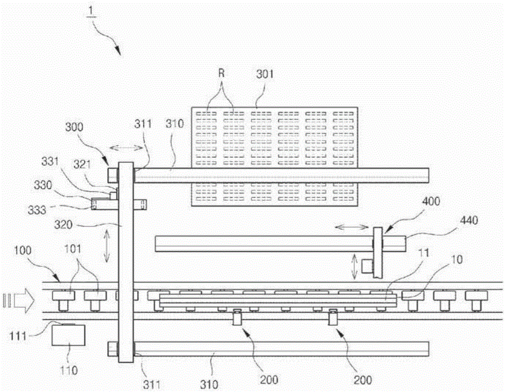
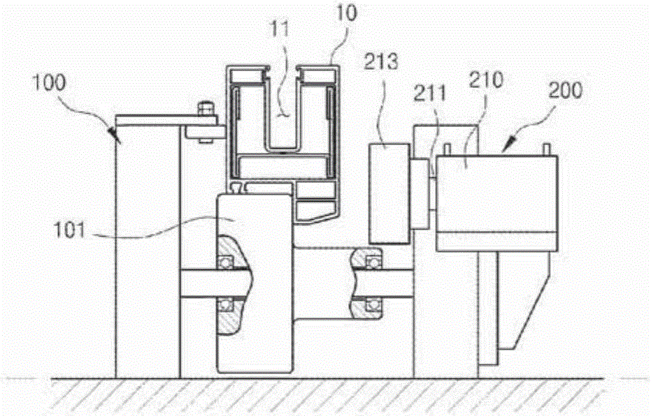
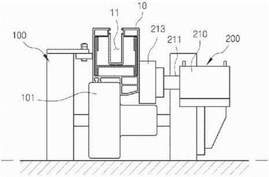
[0027] Preferred embodiments of the present invention will now be described in detail with reference to the accompanying drawings.

[0028] In the drawings, the same components have the same reference numerals even if they are shown in different drawings.

[0029] figure 1 It is a schematic diagram showing the overall structure of a roller assembly machine for windows according to a preferred embodiment of the present invention; Figure 2a and 2b is a view showing an operational state of the clamping portion of the roller assembly machine; Figures 3a to 3c is a view showing an operational state of the roller supply portion according to the preferred embodiment of the present invention; and Figures 4a to 4c is a view showing one operational state of the joint member assembly portion according to the preferred embodiment of the present invention.

[0030] refer to figure 1 , the roller assembly machine 1 according to the preferred embodiment of the present invention inclu...


PUM


Abstract

Disclosed therein is a roller assembly machine for window, which can automatically locate a roller into a seating recess of a window profile and fix the located roller by means of a joining member. The roller assembly machine for window includes: a conveying part(100) for conveying a profile(10) for manufacturing a window to one side; a clamping part(200) for fixing the conveyed profile(10) at a predetermined position; a roller supply part(300) for positioning at least one roller assembly(R) on a seating recess(11) of the fixed profile(10); and a joining member assembly part(400) for fixing the roller assembly(R) located in the seating recess(11) by means of a joining member. Because the roller supply part includes a plurality of the fingers, the plural roller assemblies are grasped from the feeder at once and sequentially located inside the seating recess of the conveyed profile. Therefore, the roller assembly machine for window according to the preferred embodiment of the present invention can reduce time and the number of work processes required for reciprocating the roller supply part, thus enhancing work efficiency.

Description

technical field [0001] The present invention relates to a roller assembling machine for a window, and more particularly, to a roller assembling machine for a window capable of easily assembling a roller to be placed at the bottom of a sliding window. Background technique [0002] Generally, buildings each have various windows or doors installed in the openings of the buildings to block the inside of the building from the outside, and in this case, the frame for supporting the windows or doors depends on the material used Classified as wood frame or metal frame. Recently, however, frames for windows or doors are made of plastic or synthetic resin such as PVC. [0003] In addition, PVC is a synthetic resin material belonging to the group of organic polymers, which is produced by treating vinyl chloride with a peroxide catalyst in an aqueous suspension or emulsion. PVC is mixed with plasticizers, stabilizers and pigments to make flexible products such as packaging films. [...

Claims


Application Information

Patent Timeline
Patent Type & Authority Applications(China)
IPC IPC(8): E05D15/06E06B3/46
CPCB23P19/04B23P2700/08
Inventor 具滋建
Owner LG HAUSYS LTD
Learn More