Flue gas desulphurization apparatus and flue gas desulphurization method

A desulfurization device and flue gas technology, applied in separation methods, chemical instruments and methods, dispersed particle separation, etc., can solve the problems of poor flue gas desulfurization effect, high cost, and high investment and maintenance costs

Active Publication Date: 2015-11-04
HEBEI WEIWO ENVIRONMENT ENG TECH CO LTD
View PDF5 Cites 2 Cited by
  • Summary
  • Abstract
  • Description
  • Claims
  • Application Information

AI Technical Summary

Problems solved by technology

[0004] The inventor of the present invention found in the research process that the current flue gas desulfurization device has the following problems: the flue gas desulfurization device needs to be equipped with a booster fan and a water cooling device, etc., and the investment and maintenance costs are relatively high, resulting in relatively high cost of desulfurization of the flue gas. At the same time, the existing flue gas desulfurization device only sprays the absorbent that reacts with sulfur dioxide through the equipped lye spray device to achieve flue gas desulfurization. This single-stage desulfurization method has poor flue gas desulfurization effect

Method used


Image

  • Flue gas desulphurization apparatus and flue gas desulphurization method
  • Flue gas desulphurization apparatus and flue gas desulphurization method
  • Flue gas desulphurization apparatus and flue gas desulphurization method

Examples


Embodiment Construction

[0045] The following will clearly and completely describe the technical solutions in the embodiments of the present invention with reference to the accompanying drawings in the embodiments of the present invention. Obviously, the described embodiments are only some, not all, embodiments of the present invention. Based on the embodiments of the present invention, all other embodiments obtained by persons of ordinary skill in the art without making creative efforts belong to the protection scope of the present invention.

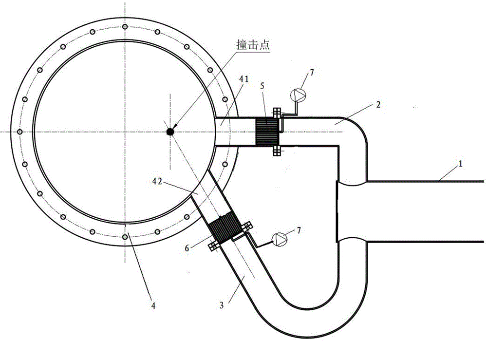
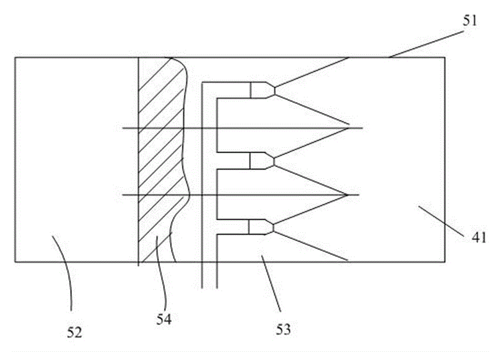
[0046] figure 1 For the schematic structural diagram of the flue gas desulfurization device provided by the embodiment of the present invention, refer to figure 1 , the flue gas desulfurization device may include: a flue 1, a first passage 2, a second passage 3, a reaction tower 4, a first scrubber 5 arranged in the first passage 2, a first scrubber 5 arranged in the second flue 3 second scrubber 6;

[0047] Wherein, the flue 1 is used to absorb flue gas;

...


PUM


Abstract

The invention provides a flue gas desulphurization apparatus, which comprises a flue capable of absorbing flue gas; a first channel and a second channel communicated with an outlet of the flue; a reaction tower; a first inlet of a tower body of the reaction tower arranged at outlet of the first channel, a second inlet of the tower body of the reaction tower arranged at outlet of the second channel, a first scrubber arranged on the first channel, performing desulphurization washing on the flue gas in the first channel from the flue, and spraying the high pressure gas-liquid mixing flow after washing from the first inlet; and a second scrubber arranged on the second channel, performing desulphurization washing on the flue gas in the second channel from the flue, and spraying the high pressure gas-liquid mixing flow after washing from the second inlet. The flue gas desulphurization apparatus can realize multitime desulphurization on flue gas, and flue gas desulphurization can be thoroughly completed.

Description

technical field [0001] The invention relates to the technical field of flue gas treatment, in particular to a flue gas desulfurization device and a flue gas desulfurization method. Background technique [0002] The flue gas desulfurization device is a device for filtering and removing sulfur dioxide from the flue gas generated during the thermal power generation process and the working process of industrial furnaces. Filter and remove sulfur dioxide from flue gas; the use of flue gas desulfurization devices is of great significance for purifying air, controlling the formation of acid rain, and protecting the environment. [0003] At present, the commonly used desulfurization process is wet desulfurization process. The principle of the process is that the flue gas discharged from the flue is pressurized by the booster fan, cooled by the cooling device, and then enters the reaction tower for reaction and absorption. The sulfur dioxide in the flue gas is mixed with alkaline slu...

Claims


Application Information

Patent Timeline
Patent Type & Authority Applications(China)
IPC IPC(8): B01D53/80B01D53/50
Inventor 李玉亮毯大鹏刘铭王曦刘涛李阳
Owner HEBEI WEIWO ENVIRONMENT ENG TECH CO LTD
Why Eureka
Try Eureka