Electroplating device

An electroplating device and electroplating solution technology, applied in the direction of electrodes, electrolysis process, electrolysis components, etc., can solve the problem of limited effect of anode material consumption

Active Publication Date: 2015-11-04
BOARDTEK ELECTRONICS CORP
View PDF7 Cites 2 Cited by
  • Summary
  • Abstract
  • Description
  • Claims
  • Application Information

AI Technical Summary

Problems solved by technology

[0005] However, such an approach has a limited effect on reducing the loss of anode materials. Therefore, how to effectively reduce the loss of anode materials caused by the use of organic additives has long been an urgent issue in the industry.

Method used


Image

  • Electroplating device
  • Electroplating device
  • Electroplating device

Examples


Embodiment Construction

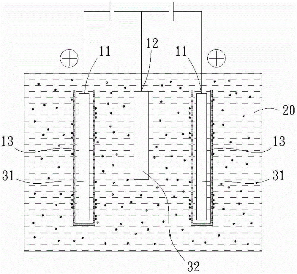
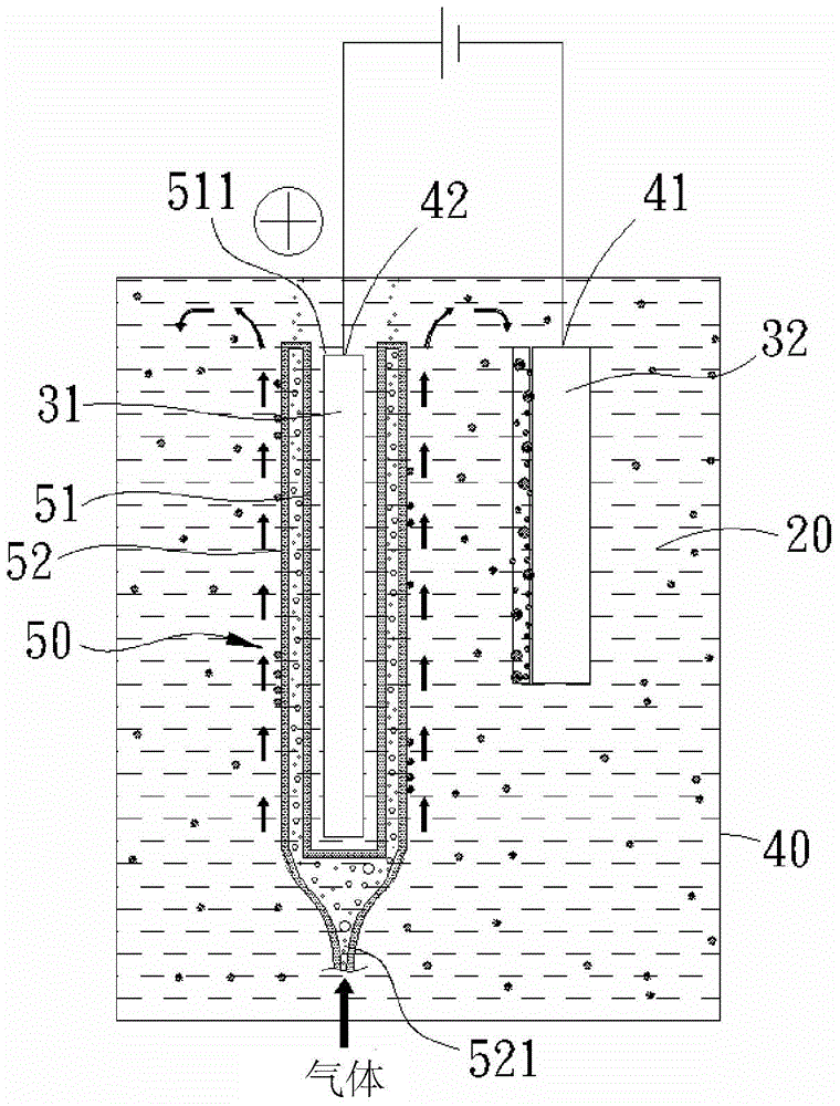
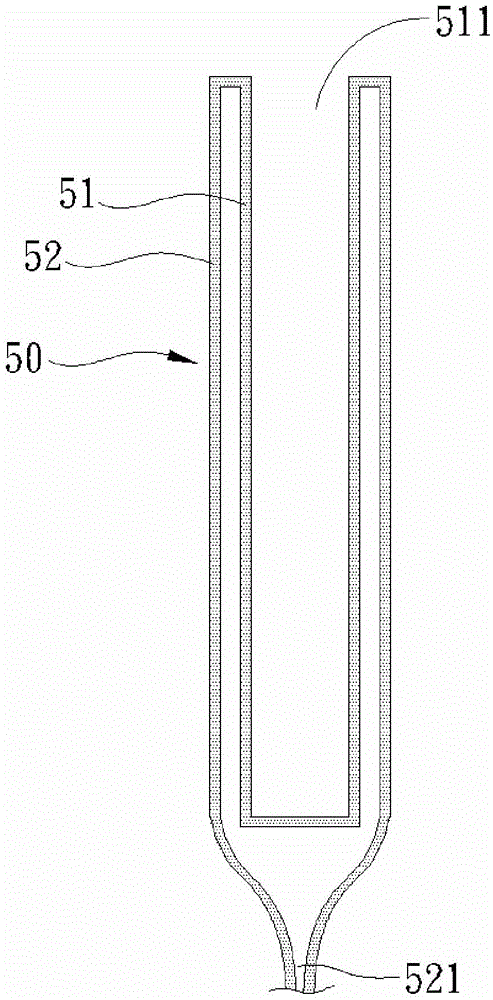
[0036] The present invention mainly provides an electroplating device that can effectively reduce the loss of anode materials and additives, and is especially suitable for electroplating operations using organic additives, such as figure 2 Schematic diagram of the electroplating device structure of the first embodiment of the present invention, image 3 As shown in the cross-sectional view of the structure of the compound filter bag in the present invention, the electroplating device of the present invention basically has a tank body 40 for containing the electroplating solution 20, and at least one negative electrode for connecting the object to be plated 32 is provided in the tank body 40. electrode 41, and at least one positive electrode 42 for connecting to the anode material 31.

[0037] The present invention is characterized in that: the electroplating device is provided with a composite filter bag 50 that can penetrate the electroplating solution at the at least one po...


PUM


Abstract

The invention discloses an electroplating device. At least one positive electrode of the electroplating device is provided with a compound filter bag through which an electroplating solution can penetrate. Each compound filter bag is provided with an inner bag body and an outer bag body, wherein the inner bag body is located in the inner layer, the outer bag body relatively wraps the inner bag body, the bottom of the inner bag body is closed, and only the top of the inner bag body is provided with a placement opening in which an anode material correspondingly extends. A preset distance is kept between the outer bag body and the inner bag body. An air inlet for being connected with an air source is formed in the bottom of the outer bag body. In the electroplating process, the air source can be guided into the compound filter bags wrapping the anode materials, then a bubble thin film wrapping the anode materials is formed, and therefore anode material losses and additive consumption are reduced more actively and reliably.

Description

technical field [0001] The invention relates to an electroplating device, in particular to an electroplating device which can effectively reduce the consumption of anode materials and additives. Background technique [0002] Press, the general electroplating process is mainly through the electrolysis process. After the voltage is input between the anode and the cathode, the metal ions in the electroplating solution are attracted to swim to the cathode, and after reduction, they are plated on the plated object connected to the cathode. At the same time, the metal ions connected to the anode The metal redissolves to provide more metal ions in the electroplating solution, so that the electrolysis process continues until sufficient coating is deposited on the plated object. [0003] Known as figure 1 As shown, an insoluble anode material 31 is connected to the anode contact 11 connected to the positive charge, and the metal ions in the electroplating solution 20 are supplemente...

Claims


Application Information

Patent Timeline
IPC IPC(8): C25D17/10C25D21/06
Inventor 郑文锋许吉昌袁维励游辉鑫
Owner BOARDTEK ELECTRONICS CORP
Why Eureka
Try Eureka