An electric auxiliary power automatic water adding device

An automatic water-filling and electric-assisted technology, applied in the configuration of water supply devices, water supply devices, and water supply pools, etc., can solve the problems of high circuit failure rate, inapplicability, and cannot be counted as a constant-position water supply device, etc., to reduce the circuit failure rate. , to avoid the effect of frequent switching

Inactive Publication Date: 2016-10-12
INST OF SOIL SCI CHINESE ACAD OF SCI
View PDF7 Cites 0 Cited by
  • Summary
  • Abstract
  • Description
  • Claims
  • Application Information

AI Technical Summary

Problems solved by technology

[0002] Known electric auxiliary power automatic water adding devices generally have the either-or problem of upper and lower water levels and frequent switching circuits: for example, the device shown in the authorized announcement number CN 100514239c, although it avoids the high failure rate caused by frequent switching of the circuit , but because it has upper and lower water levels, it cannot be regarded as a constant water adding device in the strict sense. For example, the device shown in the authorized announcement number CN101566387 can keep the water level basically constant, but it is at the cost of a high failure rate of the circuit; in addition, Some have no auxiliary power unit, as shown in the publication number cn94108500, although the water level can be kept constant, but due to the limited amount of water in the bucket at one time, manual water replenishment is required in the middle, so it is not suitable for a large amount of water supply for a long time

Method used


Image

  • An electric auxiliary power automatic water adding device
  • An electric auxiliary power automatic water adding device
  • An electric auxiliary power automatic water adding device

Examples


Embodiment 1

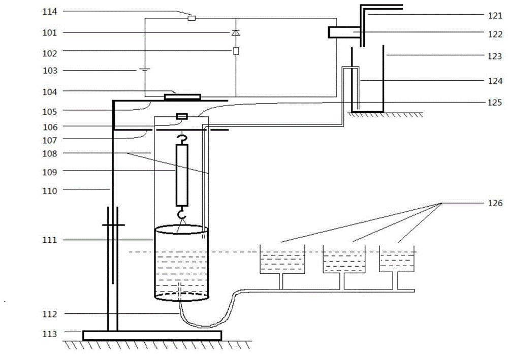
[0036] Such as figure 1 As shown, an automatic water filling device with electric auxiliary power includes a bracket, a spring 109, a bucket 111, a normally open magnetic switch, a water delivery module, a water pipe 121, a normally closed electromagnetic water valve 122, and a normally open magnetic control switch. The circuit of the switch and the normally open magnetic control switch connects the water bucket 111 and the hose 112 of the downstream water consumption device 126; the upper end of the spring 109 is hung on the bracket, and the lower end hangs the water bucket 111; the inside of the water bucket 111 is a cylinder or a cuboid, horizontally horizontal The size of the cross-sectional area is set so that the water weight per unit depth equals the force required for the deformation of the spring 109 units, that is, K=ρgs (k is the elastic coefficient of the spring 109, g is the acceleration of gravity, and s is the transverse direction of the horizontal direction insi...

Embodiment 2

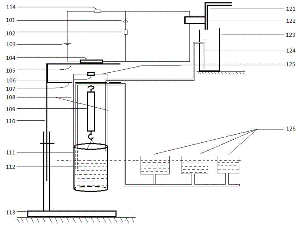
[0047] refer to figure 2 , the structure and principle of this embodiment are basically the same as that of Embodiment 1, the difference is that one end of the hose 112 of this embodiment is suspended from the lower beam 107 of the support and stretched into the water of the bucket 111, and one end is connected to the water of the downstream water consumption device 126, When using for the first time, the hose should exhaust the air and then siphon the water in the bucket 111 into the downstream water consumption device 126; the hose 112 does not touch the bucket wall, bucket bottom or bucket handle of the bucket 111;

[0048] The normally open magnetic control switch in this embodiment can also be changed to a normally closed magnetic control switch, and the corresponding normally closed electromagnetic water valve should be changed to a normally open electromagnetic water valve; in addition, the circuit controlled by the magnetic control switch can not It is directly connec...

Embodiment 3

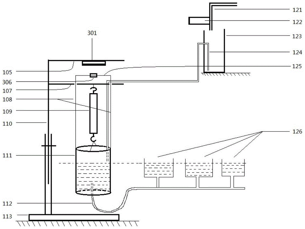
[0050] The structure and principle of this embodiment are basically the same as that of Embodiment 1, the difference is: 1. Refer to Figure 3-1 , the proximity switch of the present embodiment is a normally open capacitive proximity switch 301, a DC two-wire type; two, refer to Figure 3-2 , the circuit connection method is slightly different: the circuit where the normally open capacitive proximity switch 301 is located is not directly connected with the electromagnetic water valve 122, but forms a control circuit with the electromagnet of the electromagnetic relay 001, and then controls the electromagnetic water valve through the electromagnetic relay 001 The working circuit where 122 is located;

[0051] Capacitive proximity switch 301 installation method: refer to Figure 3-1 , the normally open capacitive proximity switch 301 is fixed on the lower surface of the upper beam 105, and the dielectric substance 306 is sheathed on the horizontal thin rod 125 such as an iron r...


PUM


Abstract

The invention discloses an automatic water adding device with auxiliary electric power. The automatic water adding device is mainly formed by a support, a spring, a water bucket, a control circuit where a proximity switch is located, a water conveying module, an electromagnetic water valve and a hose. According to the situation that the specific gravity of a work water body is fixed, the constant level of the work water surface elevation can be maintained as long as the length change of the spring and the depth change of the water body in the hung water bucket are maintained to be identical, then, along with consumption of the water in the water bucket, the proximity switch is triggered when the water bucket ascends to the set height, the electromagnetic water valve is used for pouring water with the set volume into the container at a time through the water conveying module, the water bucket descends accordingly, and the work water surface elevation is continuously maintained to be unchanged. According to the automatic water adding device, the constant level of the water surface is achieved, and the division of an upper water level and a lower water level does not exist; furthermore, the water with the quantification volume is added at a time through the water conveying module, it is avoided that the circuit of the device is frequently closed and opened at the set water surface elevation, and the fault rate of the circuit is greatly reduced.

Description

technical field [0001] The invention relates to an automatic water adding device with auxiliary power, in particular to an automatic water adding device with electric auxiliary power to keep the water level constant. Background technique [0002] Known electric auxiliary power automatic water adding devices generally have the either-or problem of upper and lower water levels and frequent switching circuits: for example, the device shown in the authorized announcement number CN 100514239c, although it avoids the high failure rate caused by frequent switching of the circuit , but because it has upper and lower water levels, it cannot be regarded as a constant water adding device in the strict sense. For example, the device shown in the authorized announcement number CN101566387 can keep the water level basically constant, but it is at the cost of a high failure rate of the circuit; in addition, Some do not have auxiliary power unit, as shown in publication number cn94108500, t...

Claims


Application Information

Patent Timeline
Patent Type & Authority Patents(China)
IPC IPC(8): E03B1/00E03B11/00E03B7/07
Inventor 郑继成王德建王灿张刚张丽霞郭志英
Owner INST OF SOIL SCI CHINESE ACAD OF SCI
Why Eureka
Try Eureka