
Scroll compressor

A scroll compressor, scroll technology, applied in the direction of rotary piston machinery, rotary piston pump, mechanical equipment, etc., can solve the problems of reducing compressor operating efficiency, noise, large compressor initial torque, etc. The effect of improving startup reliability

Active Publication Date: 2015-11-04
LG ELECTRONICS INC
View PDF4 Cites 0 Cited by
  • Summary
  • Abstract
  • Description
  • Claims
  • Application Information

AI Technical Summary

Problems solved by technology

Eventually, the discharge path of the discharge-side refrigerant is blocked, and the above-mentioned discharge-side refrigerant cannot be discharged toward the suction side of the compressor, and the fixed scroll is pressed further downward.
[0014] As described above, if the fixed scroll is pressurized and maintained in close contact with the orbiting scroll at a predetermined level or higher, it is difficult to quickly restart the scroll compressor.
As a result, in order to be able to quickly restart the scroll compressor, a large initial torque of the compressor is required, and when the initial torque becomes large, noise and wear are generated, and the operating efficiency of the compressor is reduced

Method used


Image

  • Scroll compressor
  • Scroll compressor
  • Scroll compressor

Examples


Embodiment Construction

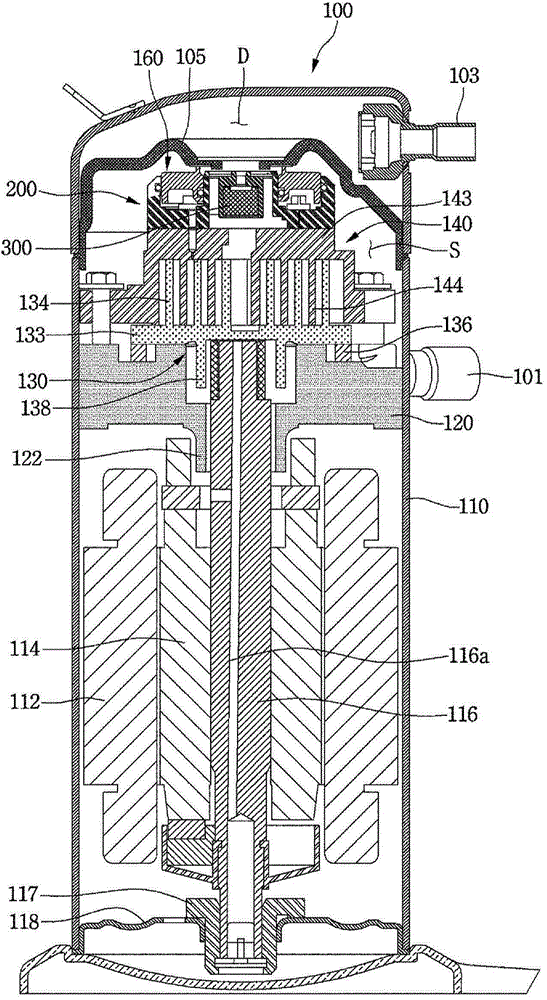
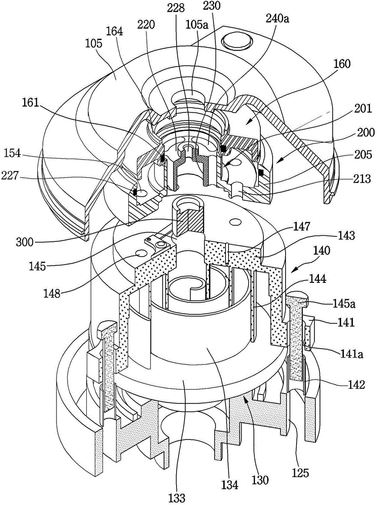
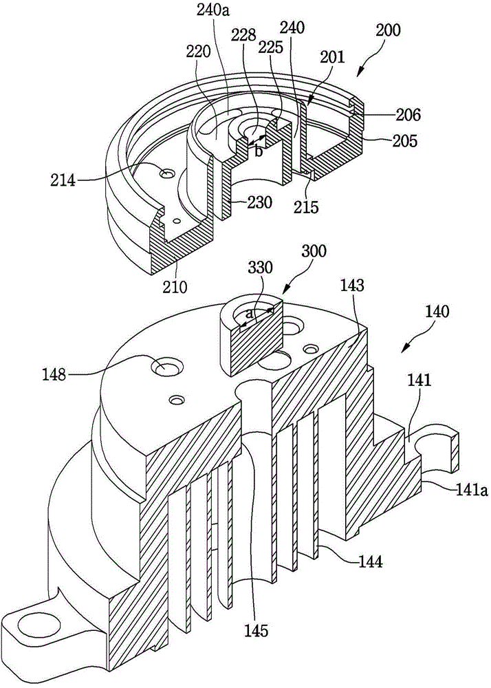
[0061] figure 1 To show a cross-sectional view of the structure of the scroll compressor of the first embodiment of the present invention, figure 2 In order to explode a cross-sectional view showing a part of the structure of the scroll compressor of the first embodiment of the present invention, image 3 In order to show an exploded perspective view of the structure of the back pressure part and the fixed scroll of the first embodiment of the present invention, Figure 4 It is a diagram showing the structure of the opening and closing device of the first embodiment of the present invention.

[0062] Reference Figure 1 to Figure 3 , The scroll compressor 100 of the first embodiment of the present invention includes a casing 110 for forming a suction space S and a discharge space D.

[0063] In detail, a cover 105 is provided on the upper part of the inside of the housing 110. With the cover 105, the internal space of the housing 110 is divided into a suction space S and a discharg...


PUM


Abstract

A scroll compressor is provided that may include a casing including a rotational shaft, a cover fixed inside of the casing to partition the inside of the casing into a suction space and a discharge space, a first scroll revolved by rotation of the rotational shaft, a second scroll disposed on or at one side of the first scroll to define a compression chamber together with the first scroll, the second scroll including a discharge, through which a refrigerant pressed in the compression chamber may be discharged, a switching device movably disposed on or at one side of the discharge to selectively open and close the discharge, a back pressure portion including a moving guide that accommodates at least a portion of the switching device, and a top surface that covers one side of the switching device; and an adhesion preventer that reduces a contact area between the switching device and at least a portion of the back pressure portion.

Description

Technical field [0001] The invention relates to a scroll compressor. Background technique [0002] The scroll compressor, as a compressor using a fixed scroll having a spiral scroll portion and a orbiting scroll relative to the above-mentioned fixed scroll, follows the fixed scroll and the orbiting scroll. The disk rotates in an intermeshing manner, so that the volume of the compression chamber formed between the fixed scroll and the orbiting scroll decreases with the orbiting motion of the orbiting scroll, and the pressure of the fluid rises accordingly, and from the perforation to the fixed A compressor that discharges fluid from the discharge port in the center of the scroll. [0003] This scroll compressor has the feature of continuous suction, compression and discharge during the orbiting scroll of the orbiting scroll. Therefore, in principle, there is no need to provide a discharge valve and a suction valve. Moreover, it not only has a simple structure due to the small numb...

Claims


Application Information

Patent Timeline
Patent Type & Authority Applications(China)
IPC IPC(8): F04C18/02F04C29/00
CPCF04C27/005F04C18/0215F04C23/008F04C28/24F04C28/26F04C29/124
Inventor 尹周焕金泰渊金洙喆陈弘均
Owner LG ELECTRONICS INC
Learn More