Eureka AIR delivers breakthrough ideas for toughest innovation challenges, trusted by R&D personnel around the world.

Cabling method

A technology for laying cables and cables, applied in the best cable laying field, can solve the problem of high cost of cable laying, and achieve the effect of short cable length and improved maintainability

Inactive Publication Date: 2015-11-04
SIEMENS AG
View PDF3 Cites 0 Cited by
  • Summary
  • Abstract
  • Description
  • Claims
  • Application Information

AI Technical Summary

Problems solved by technology

[0007] However, the cost of determining optimal cabling for tens, hundreds, or even thousands of cells can be so large that modern computing facilities cannot themselves determine optimal solutions for all cells in a reasonable amount of time.

Method used


Image

  • Cabling method
  • Cabling method
  • Cabling method

Examples


Embodiment Construction

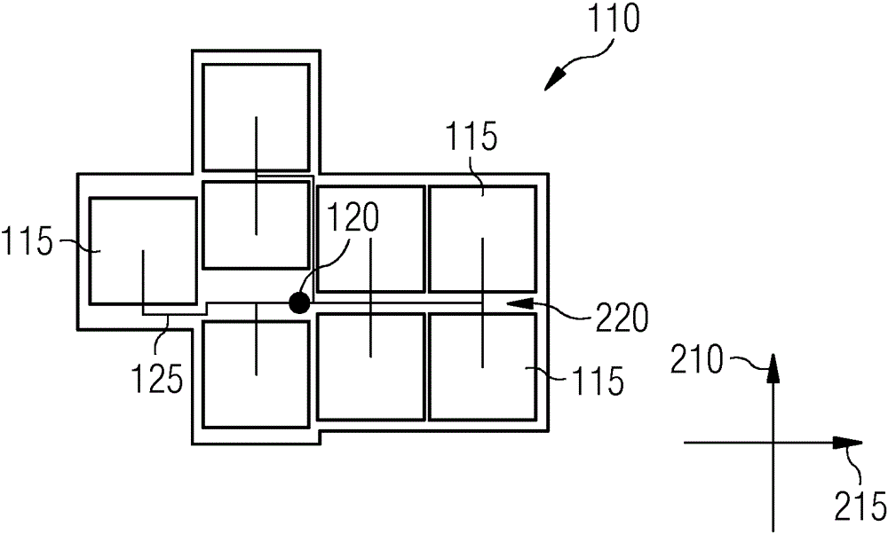
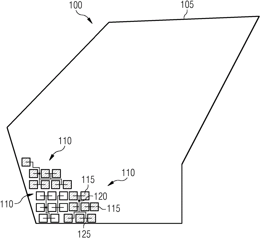
[0027] figure 1 A schematic diagram of a photovoltaic installation 100 is shown. Units 110 are arranged on the available base surface 105, and the units respectively include a plurality of solar modules 115. For reasons of clarity, only three units 110 each with six solar modules 115 are shown by way of example. Each unit 110 is also assigned a handover point 120.

[0028] In one embodiment, each solar module 115 includes one or more solar modules, which respectively include operable units of solar cells, which are usually arranged in a frame and covered with a glass plate. However, the solar module can also integrate multiple solar cells within one solar module or multiple solar modules. The handover point 120 is used for the cascade of the units 110 divided into levels. All the solar components 115 of the unit 110 are connected to the junction 120 by cables 125. An electrical component, such as an inverter (Inverter), may be provided on the handover point 120 to convert the...


PUM


Abstract

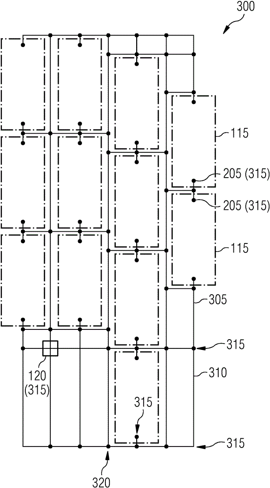
The invention relates to a method for determining a cabling of a unit of a photovoltaic system, said unit comprising a number of solar components and a transfer point. The method includes the steps of generating a cabling chart with paths between a connection of each solar component and the transfer point according to specified cable routing regulations, determining preferred paths of each solar component to the transfer point on the basis of the cabling charts, and selecting one of the determined paths for each solar component such that the cabling complexity for the unit is minimized as much as possible. In the process, the cabling complexity is determined on the basis of the sum of the lengths of the selected paths and the length of a cable channel in which the cables run individually or in a bundled manner.

Description

Technical field [0001] The invention relates to a method for laying cables. The present invention particularly relates to a method for determining the optimal cable laying on photovoltaic installations. Background technique [0002] Photovoltaic facilities are divided into one or more units, where each unit is composed of multiple solar modules and junctions. The solar module may be, for example, a solar module, each of which includes a plurality of solar cells with a glass dust cover and a mounting frame. In other embodiments, the solar components can also be determined differently, for example, by multiple solar modules or multiple solar cells. The solar modules can be fixedly oriented in a predetermined direction, or track the apparent height of the sun individually or collectively. If the solar modules are fixedly installed, the junction points of the units are usually arranged regularly and the units do not change in their structure, so that the cable laying can be unifor...

Claims


Application Information

Patent Timeline
IPC IPC(8): G06Q10/04
CPCG06Q10/04Y02E10/50H02S40/36
Inventor P.鲍尔P.菲格
Owner SIEMENS AG
Why Eureka
Eureka Blog
Learn More