Automatic polishing device of punch for glass die

A glass mold and automatic polishing technology, which is applied to grinding drive devices, surface-polished machine tools, grinding/polishing equipment, etc., can solve the problems of worker fatigue, high work intensity, hidden dangers of work installation, etc., so as to reduce workers' work Strength, saving human resources, ensuring the effect of polishing quality

Active Publication Date: 2015-11-11
CHANGSHU JIANHUA MOLD TECH
View PDF9 Cites 6 Cited by
  • Summary
  • Abstract
  • Description
  • Claims
  • Application Information

AI Technical Summary

Problems solved by technology

[0005] The above-mentioned polishing method has the following disadvantages: first, it is not conducive to saving valuable labor resources because it needs to be polished by manpower; Whether it is the former method where the worker holds the polishing medium or the latter method, the worker holds the punch by hand, there are hidden dangers in the operation and installation, because it is inevitable that the fingers will touch the rotating parts; Fourth, due to the need for manual and machine polishing, polishing Efficiency is affected; Fifth, the quality of polishing is difficult to guarantee, because the quality of polishing of punches is related to the experience, sense of responsibility, emotion and even physical fitness of workers to a certain extent
[0006] Although all the technical information about the processing method of the punch can be seen in the published Chinese and foreign patent documents, such as the Chinese patent application publication number CN102626847A and the U.S. patent US3768343A, there is no enlightenment that can be used for reference in the automatic polishing of the punch

Method used


Image

  • Automatic polishing device of punch for glass die
  • Automatic polishing device of punch for glass die

Examples


Embodiment Construction

[0022]In order to enable the examiners of the patent office, especially the public, to understand the technical essence and beneficial effects of the present invention more clearly, the applicant will describe in detail the following in the form of examples, but none of the descriptions to the examples is an explanation of the solutions of the present invention. Any equivalent transformation made according to the concept of the present invention which is merely formal but not substantive shall be regarded as the scope of the technical solution of the present invention.

[0023] In the following descriptions, all concepts involving up, down, left, right, front and rear directionality (or orientation) are for the position state of the picture being described, and the purpose is to facilitate the public Therefore, it cannot be understood as a special limitation on the technical solution provided by the present invention.

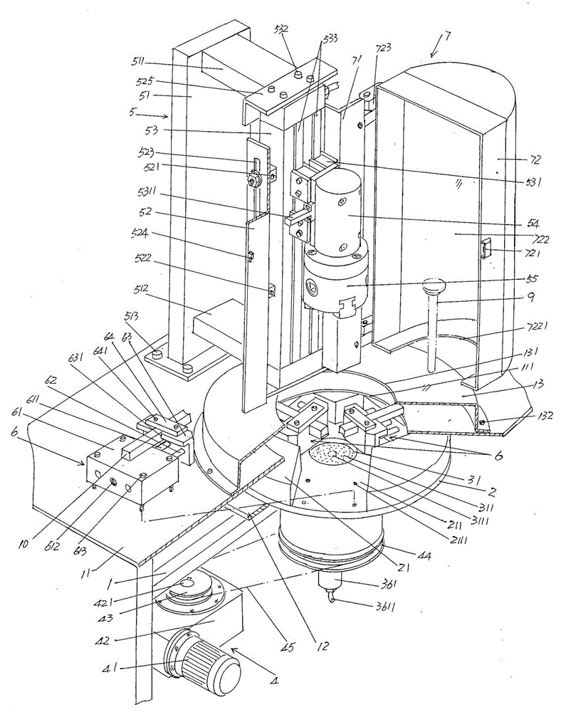
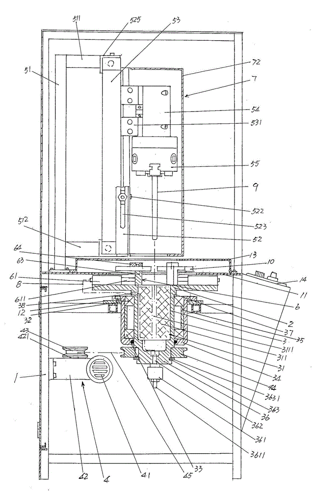
[0024] See figure 1 with figure 2 , provides a frame 1...


PUM


Abstract

The invention belongs to the technical field of machining facilities for auxiliary glass die components, and relates to an automatic polishing device of a punch for a glass die. The automatic polishing device comprises a rack, a power transmission mechanism, a punch vertical reciprocating motion mechanism and a polishing medium horizontal reciprocating motion mechanism which is fixed to a rotary disk. A table panel is fixed to the upper portion of the rack and provided with a table panel receding cavity. A rotary disk is located below the table panel. Acting cylinder limiting bases are fixed to the edge part of the side, facing the table panel, of the rotary disk. An acting cylinder limiting cavity is formed by the space between every two adjacent acting cylinder limiting bases. An oil cup is directly formed on the downward side of the rotary disk corresponding to the center position of the rotary disk. An oil cup cavity corresponds to the center of the table panel receding cavity. The power transmission mechanism is arranged on the rack and connected with the oil cup. The punch vertical reciprocating mechanism is arranged on the table panel and corresponds to the center of the table panel receding cavity. Labor resources are saved. The operation intensity of workers is relieved, and safety is guaranteed. The polishing quality on the punch is guaranteed.

Description

technical field [0001] The invention belongs to the technical field of glass mold auxiliary parts processing facilities, and in particular relates to an automatic polishing device for punches used in glass molds. Background technique [0002] The function of the punch on the glass mold is well known in the industry, and it is an essential part for the production of glass containers such as glass bottles by the small mouth pressure blowing method. When a pair of opposing half-molds (customarily called half-molds in the industry) are closed, the molten glass is introduced into the cavity of the half-mold, and the high-temperature glass frit in the molten state will be placed in the first mold. The punch in the half mold cavity is completely or partially (depending on the different glass container products) wrapped, and then the punch is rapidly cooled by the punch cooler in the punch cavity of the punch, so that the previously wrapped on the outer wall of the punch The molten...

Claims


Application Information

Patent Timeline
Patent Type & Authority Applications(China)
IPC IPC(8): B24B29/02B24B47/12B24B41/06B24B41/00
CPCB24B29/02B24B41/00B24B41/06B24B47/12
Inventor 晏庆宝马军英韩志强王永泉方朝辉黄晓磊
Owner CHANGSHU JIANHUA MOLD TECH
Why Eureka
Try Eureka