System for taking toothbrush handles from horizontal machine, shearing toothbrush handles, placing toothbrush handles into vertical machine for secondary glue injection, and conducting casing

The technology of a horizontal machine and a vertical machine, applied in the direction of coating, etc., can solve the problems of low work efficiency, high labor cost, not in line with the high efficiency of toothbrushes, low cost, etc., to improve production efficiency, high degree of automation, and reduce labor. The effect of usage

Active Publication Date: 2015-11-11
SUZHOU IND PARK CHAOQUN AUTOMATION EQUIP
View PDF4 Cites 3 Cited by
  • Summary
  • Abstract
  • Description
  • Claims
  • Application Information

AI Technical Summary

Problems solved by technology

The production of toothbrushes is roughly divided into processes such as mold opening, injection molding, wool planting, heat sealing, testing, and packing. Each process is equipped with corresponding production machines. However, most of the commonly used machines are semi-automatic and require personnel assistance to complete the process.
[0003] For example, the process of injection molding after mold opening of the toothbrush handle includes the following process

Method used


Image

  • System for taking toothbrush handles from horizontal machine, shearing toothbrush handles, placing toothbrush handles into vertical machine for secondary glue injection, and conducting casing
  • System for taking toothbrush handles from horizontal machine, shearing toothbrush handles, placing toothbrush handles into vertical machine for secondary glue injection, and conducting casing
  • System for taking toothbrush handles from horizontal machine, shearing toothbrush handles, placing toothbrush handles into vertical machine for secondary glue injection, and conducting casing

Examples


Example Embodiment

[0027] Example

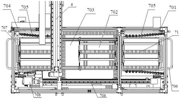
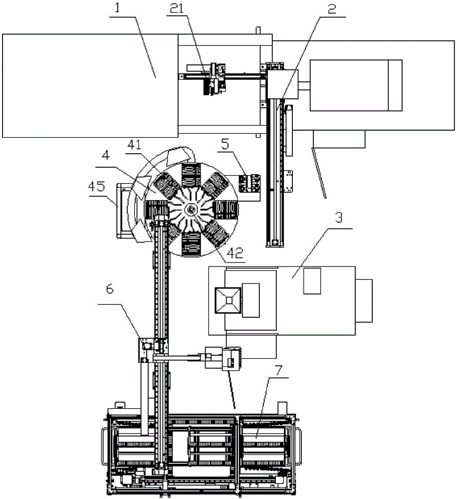
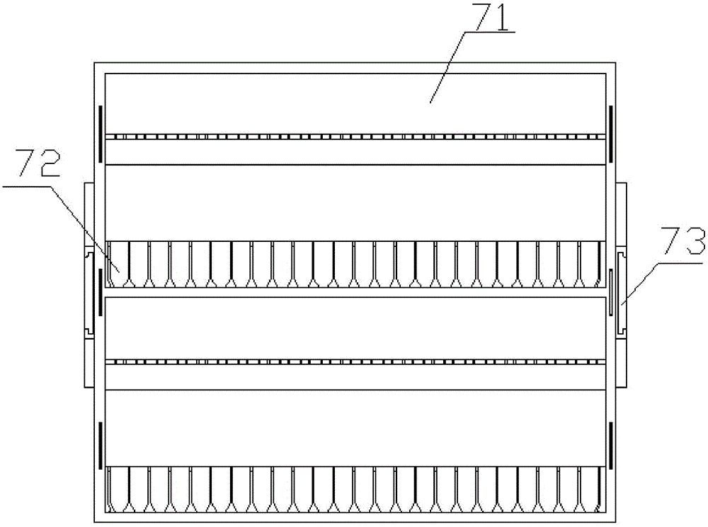
[0028] Such as Figure 1-5 As shown, this embodiment discloses a secondary glue-injecting and packing system for tooth handles taken from a horizontal machine and placed into a vertical machine. According to the procedures of the system, the system includes: a three-axis full-servo manipulator 2, an air scissors jig 5. Rotary conveyor 4, vertical injection molding machine 3, three-axis full-servo truss robot 6 and automatic stacker 7, the above-mentioned three-axis full-servo manipulator 2 grabs a number of brushes from the mold opening 1 through the grab fixture 21 The handle is moved to the air shear fixture 5. The air shear 51 on the air shear fixture 5 cuts the material head of the brush handle, and then puts the cut brush handle on the above-mentioned rotary conveyor 5. The rotary conveyor 5 is equipped with There is a cooler, the sizing brush handle is cooled on the rotary conveyor 5, the three-axis full-servo manipulator 2 places the material head in the ...


PUM


Abstract

The invention relates to system for taking toothbrush handles from a horizontal machine, shearing the toothbrush handles, placing the toothbrush handles into a vertical machine for secondary glue injection, and conducting casing. The system comprises a three-axis full-servo mechanical arm, an air shear jig, a rotating conveyer, a vertical injection molding machine, a three-axis full-servo truss robot and an automatic stacker. A plurality of toothbrush handles are grabbed through the three-axis full-servo mechanical arm from the interior of a mold opening die and then moved onto the air shear jig, stub bars of the toothbrush handles are sheared off through an air shear, and then the sheared toothbrush handles are placed on the rotating conveyer, cooled on the rotating conveyer and conveyed to an automatic feeding standby position of the vertical injection molding machine in the rotating process of the rotating conveyer; then, the toothbrush handles are grabbed and sent into a cavity of the vertical injection molding machine through the three-axis full-servo truss robot, and after injection molding is completed, the toothbrush handles are taken out and sent into a tray of the automatic stacker through the three-axis full-servo truss robot; automatic tray exchange is achieved through the automatic stacker, and then automatic casing is achieved. The system is high in automation degree, the usage rate of manpower is reduced, production efficiency is improved, and production cost is reduced relatively.

Description

technical field [0001] The invention belongs to the field of toothbrush production, in particular to a toothbrush production device, in particular to a tooth handle that is taken out by a horizontal machine and put into a vertical machine for secondary glue injection and boxing. Background technique [0002] Toothbrush is a must-have in people's life, and it is also a consumable. Therefore, the market has a large demand for toothbrushes. Improving the production efficiency of toothbrushes and relatively reducing costs are the keys to the sustainable development of toothbrush manufacturers. The production of toothbrushes is roughly divided into processes such as mold opening, injection molding, wool planting, heat sealing, testing, and packing. Each process is equipped with corresponding production machines. However, most of the commonly used machines are semi-automatic and require personnel assistance to complete the process. . [0003] For example, the process of injection...

Claims


Application Information

Patent Timeline
IPC IPC(8): B29C45/14B29C45/17B29C45/42
CPCB29C45/14008B29C45/1769B29C45/42
Inventor 夏金良何超张新
Owner SUZHOU IND PARK CHAOQUN AUTOMATION EQUIP
Why Eureka
Try Eureka