Box stop device

A technology of supporting shafts and supporting frames, which is applied in the field of palletizing, can solve the problems of high production cost and complex structure, and achieve the effects of simplifying the structure, improving conveying efficiency, and improving palletizing efficiency

Active Publication Date: 2015-11-11
JIANGSU NEWAMSTAR PACKAGING MACHINERY
View PDF9 Cites 4 Cited by
  • Summary
  • Abstract
  • Description
  • Claims
  • Application Information

AI Technical Summary

Problems solved by technology

The structure of the traditional box stop device is complex and the production cost is high

Method used


Image

  • Box stop device
  • Box stop device
  • Box stop device

Examples


Embodiment Construction

[0013] The present invention will be further described in detail below in conjunction with the accompanying drawings and preferred embodiments.

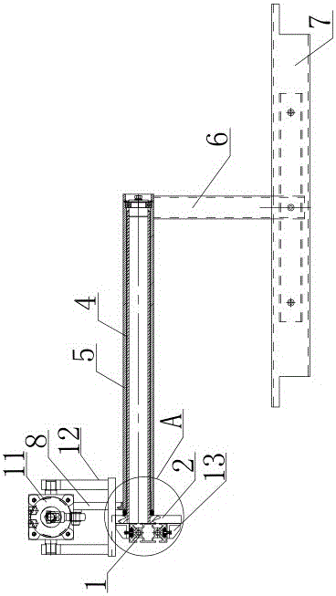
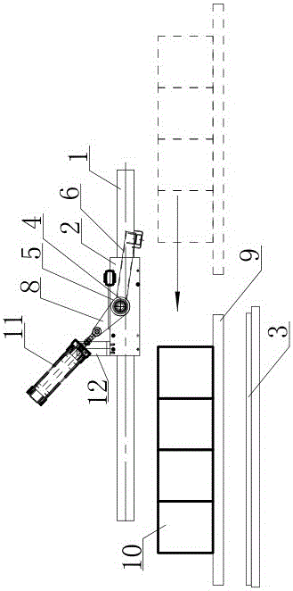
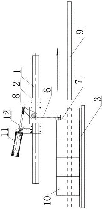
[0014] Such as figure 1 , figure 2 , image 3 , Figure 4 As shown, the box blocking device includes: a support frame 2 installed on the frame, the frame is not shown in the figure, the support frame 2 is located above the pedal 3, and one end of the support shaft 4 is fixedly installed on the support frame 2, the other end of the support shaft 4 protrudes outwards, the support shaft 4 is sleeved with a shaft sleeve 5, the shaft sleeve 5 can rotate on the support shaft 4, and the shaft sleeve 5 is fixedly connected with a stopper perpendicular to the shaft sleeve 5. Rod 6, the outer end of gear rod 6 is fixedly connected with baffle plate 7, also fixedly connected with swing rod 8 on the bushing 5, swing rod 8 is driven by the drive device, under the drive of drive device, swing rod 8 can drive shaft The sleeve 5 rotates forward...


PUM


Abstract

The invention discloses a box stop device. The box stop device comprises a support frame mounted on a frame, wherein a support shaft is fixedly mounted on the support frame, and is coated with a shaft sleeve; the shaft sleeve can rotate on the support shaft, and is fixedly connected with a stop rod; the outer end of the stop rod is fixedly connected with a stop plate; the shaft sleeve is fixedly connected with a swing rod; under the driving of a driving device, the swing rod can drive the shaft sleeve to forwards rotate or reversely rotate on the support shaft; the shaft sleeve forwards rotates on the support shaft so as to urge the stop plate to move to the outer side of a box on a transplantation platform positioned rightly above a stamp plate and to stop the box moving in the return direction of the transplantation platform; and the shaft sleeve reversely rotates on the support shaft so as to urge the stop plate to move to a height higher than the top of the box on the transplantation platform. The box stop device has the advantages of largely simplifying the structure, effectively stopping the box moving in the leaving direction of the transplantation platform and guaranteeing the box to accurately drop on the stamp plate.

Description

technical field [0001] The invention relates to the technical field of palletizing, in particular to a box blocking device in the palletizing process. Background technique [0002] When stacking, after the transfer platform transports the boxes with goods to the top of the pallet, the transfer platform is pulled out from the bottom of the boxes, so that the boxes on the transfer platform fall on the pallet. In order to prevent the box from moving along with the transfer platform during the pulling-out process of the transfer platform, a box stop device is usually installed above the stomping board, which blocks the box and prevents the box from moving in the direction of pulling away from the transfer platform. This ensures that the box falls accurately on the stomp board. The structure of the traditional box blocking device is complex and the manufacturing cost is high. Contents of the invention [0003] The purpose of the present invention is to provide a box blocking ...

Claims


Application Information

Patent Timeline
Patent Type & Authority Applications(China)
IPC IPC(8): B65G57/03
Inventor 黄毅峰江彩苗
Owner JIANGSU NEWAMSTAR PACKAGING MACHINERY
Why Eureka
Try Eureka