
Portable cable dereeling plate

A pay-off reel and portable technology, applied in the field of electric power, can solve the problems of inconvenient transportation and handling, time-consuming and labor-intensive construction, and low work efficiency, and achieve the effects of simple structure, improved pay-off efficiency, and convenient installation

Inactive Publication Date: 2015-11-11
牛永杰
View PDF0 Cites 5 Cited by
  • Summary
  • Abstract
  • Description
  • Claims
  • Application Information

AI Technical Summary

Problems solved by technology

[0003] The existing pay-off reels are generally large and heavy, and it is extremely inconvenient to transport and carry
When in use, multiple operators are required to adjust the height and balance of the reel, which is time-consuming and labor-intensive, and the work efficiency is low

Method used


Image

  • Portable cable dereeling plate

Examples


Embodiment

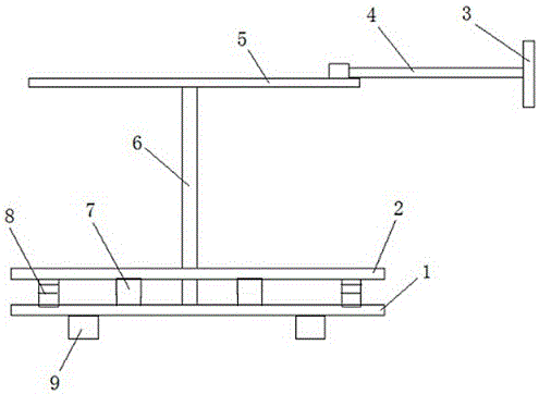
[0015] This embodiment provides a portable cable reel, such as figure 1 As shown, it includes a chassis 1 supported on the ground, the chassis 1 can increase the contact area between the cable pay-off reel and the ground, the middle part of the chassis 1 is fixed with a vertically upward fixed shaft 6, and the chassis 1 is provided with a turntable 2. The turntable 2 is sleeved on the fixed shaft 6, and the turntable 2 rotates on the chassis 1 around the fixed shaft 6. The lower surface of the turntable 2 is provided with a plurality of rollers 8 that rotate along the upper surface of the chassis 1. The rollers 8 There are six and are evenly arranged on the same circumference on the lower surface of the rotating disk 2 . A detachable top plate 5 is connected to the upper end of the fixed shaft 6, and a rotating handle is fixed on the top plate 5. The rotating handle includes a long handle 4 , one end of the long handle 4 is eccentrically fixedly connected to the top plate 5 ,...


PUM


Abstract

The invention belongs to the technical field of electricity and specifically provides a portable cable dereeling plate. The portable cable dereeling plate comprises a base plate which is supported on the ground; a fixing shaft which is straight up is fixed in the middle part of the base plate; a rotating plate which sleeves the fixing shaft is arranged on the base plate; a plurality of rollers which can rotate along the upper surface of the base plate are arranged on the lower surface of the rotating plate; a detachable top plate on which a rotating handle is fixed is connected to the upper end of the fixing shaft. The portable cable dereeling plate is simple in structure, convenient to mount and small in size; the rollers below the rotating plate can reduce the resistance in dereeling; the rotating handle can assist reeling and dereeling, so that the manpower can be saved, the dereeling speed can be controlled, and as a result, the dereeling efficiency can be increased.

Description

technical field [0001] The invention belongs to the technical field of electric power, and in particular relates to a portable cable pay-off reel. Background technique [0002] Cable replacement is a routine operation item for technical renovation and overhaul of power distribution lines. In recent years, the economic development of various regions has accelerated rapidly, and the infrastructure construction of municipalities, basic engineering, and large projects (such as urbanization electricity, road chemical industry, etc.) has been widely started. , The amount is so large that the power load of the distribution line increases, and the cables in operation are already overwhelmed. According to the prior art, the user's demand can only be increased by replacing the cables. Since the cables are wrapped in a whole bundle on the pay-off reel, the cables need to be released from the reel during use. Since the whole bundle of cables is bulky and heavy, it cannot be done manual...

Claims


Application Information

Patent Timeline
Patent Type & Authority Applications(China)
IPC IPC(8): B65H49/20
Inventor 牛永杰
Owner 牛永杰
Learn More