Balance valve group and hydraulic system

A technology of hydraulic system and balancing valve, applied in the field of hydraulic components, can solve the problem of uncontrolled retraction speed of hydraulic cylinder 4, etc.

Active Publication Date: 2015-11-11
CHANGDE ZHONGLIAN ZHONGKE HYDRAULIC +1
View PDF9 Cites 13 Cited by
  • Summary
  • Abstract
  • Description
  • Claims
  • Application Information

AI Technical Summary

Problems solved by technology

[0004] The force change of the hydraulic cylinder 4 causes the pressure of the hydraulic oil in the rodless cavity of the hydraulic cylinder 4 to change continuously. Although the opening of the spool of the balance valve 100 is constant, the pressure difference between the front and rear of the throttle port of the balance valve 100 is constantly changing. The flow rate of the luffing drop is also constantly changing, that is, the retraction speed of the hydraulic cylinder 4 is not controlled

Method used


Image

  • Balance valve group and hydraulic system
  • Balance valve group and hydraulic system
  • Balance valve group and hydraulic system

Examples


Embodiment Construction

[0070] The specific embodiments of the present invention will be described in detail below with reference to the accompanying drawings. It should be understood that the specific embodiments described herein are only used to illustrate and explain the present invention, and not to limit the present invention.

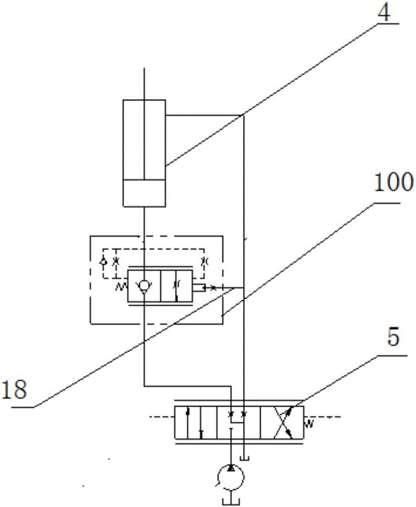
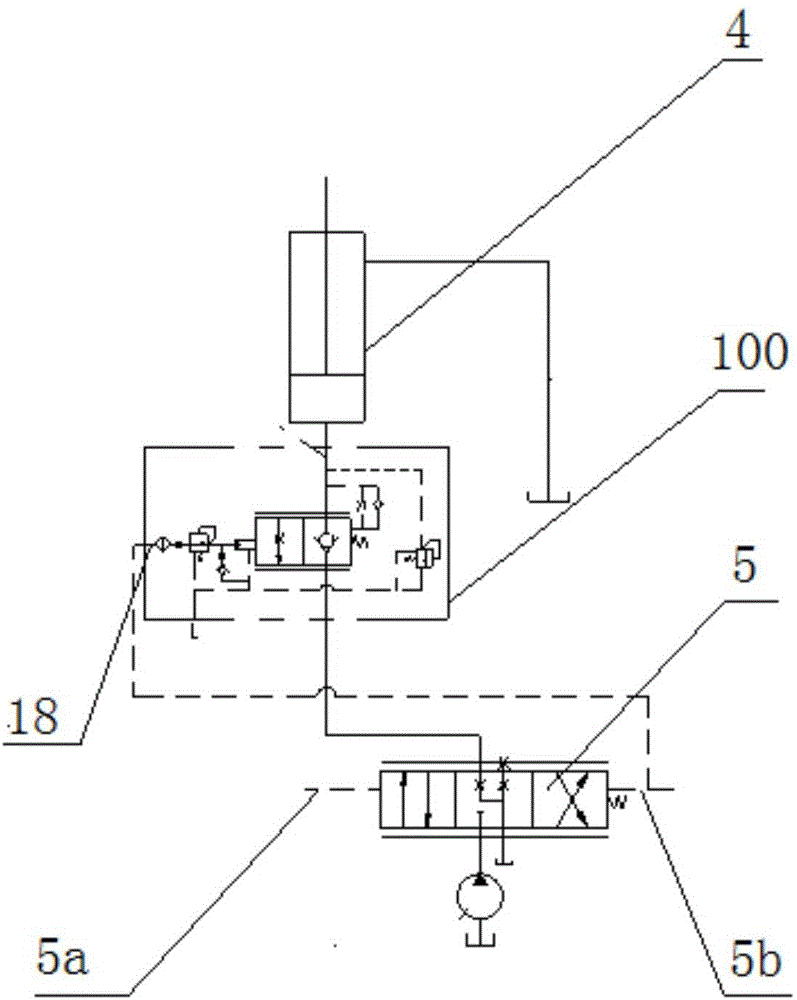
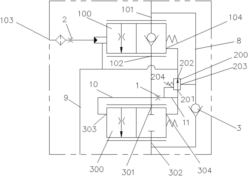
[0071] See image 3 According to one aspect of the present invention, there is provided a balance valve group, the balance valve group includes a balance valve 100, the balance valve 100 has a balance valve first working oil port 101 for opening to the load, for opening to the oil source Or the second working oil port 102 of the balance valve of the oil tank and the balance valve hydraulic control cavity 103 and the balance valve spring cavity 104 respectively located at both ends of the spool of the balance valve 100 to be able to pass through the balance valve hydraulic control cavity 103 and the balance valve spring cavity 104 Cooperate with the control balance valve 100...


PUM


Abstract

The invention discloses a balance valve group and a hydraulic system. The balance valve group comprises a balance valve (100), wherein the balance valve (100) is provided with a first balance valve working port (101) leading to loads, a second balance valve work oil opening (102) leading to an oil source or an oil tank, a balance valve hydraulic control cavity (103) and a balance valve spring cavity (104), and the balance valve hydraulic control cavity (103) and the balance valve spring cavity (104) are located at the two ends of a valve element of the balance valve (100). The balance valve group further comprises a pressure compensation device connected with the balance valve (100). Therefore, when hydraulic oil sequentially passes through the first balance valve work oil opening (101) and the second balance valve work oil opening (102) from the loads and flows back to the oil tank, the pressure difference between the first balance valve work oil opening (101) and the second balance valve work oil opening (102) keeps constant, and the flow amount of the hydraulic oil passing through the balance valve (100) depends on the position of the valve element of the balance valve instead of the pressure of the loads.

Description

Technical field [0001] The present invention relates to hydraulic components, in particular to a balance valve group and hydraulic system. Background technique [0002] The balance valve is a key hydraulic component that controls the luffing action of the truck crane. It is used in the hydraulic system of the luffing mechanism to ensure the smooth operation of the luffing mechanism. figure 1 Shows a schematic diagram of a hydraulic system of a luffing mechanism in the prior art, including a hydraulic cylinder 4 for supporting a luffing boom, a balance valve 100 and a reversing valve 5 connected according to the connection relationship shown in the figure, from figure 1 It can be seen that since the pressure of the balance valve hydraulic control oil circuit 18 corresponding to the balance valve 100 is the same as that of the rod cavity of the hydraulic cylinder 4, the pressure change in the rod cavity of the hydraulic cylinder 4 will directly affect the opening degree of the balanc...

Claims


Application Information

Patent Timeline
Patent Type & Authority Applications(China)
IPC IPC(8): B66C23/82F15B13/042
CPCB66C23/821F15B13/0426
Inventor 潘文华宋晓龙杨荣健
Owner CHANGDE ZHONGLIAN ZHONGKE HYDRAULIC
Why Eureka
Try Eureka