Raw material carrying trolley capable of automatically traveling

A technology for handling trolleys and automatic walking, applied in the direction of lifting devices, etc., can solve the problems of low efficiency, high labor intensity, and the trolley cannot be stopped stably.

Active Publication Date: 2015-11-11
浙江欧托电气有限公司
View PDF7 Cites 9 Cited by
  • Summary
  • Abstract
  • Description
  • Claims
  • Application Information

AI Technical Summary

Problems solved by technology

[0002] In chemical, pharmaceutical and other industries, it is often necessary to transport various raw materials. The existing material handling is generally carried out by manually pushing the trolley, which has low efficiency and high labor intensity. At the same time, the structure of the existing trolley is generally The lower part of the base plate is directly and simply hinged with several walking wheels. When a person pushes the trolley, the ground is uneven, which will cause the trolley to bump, causing the raw materials in the feeding barrel on it to shake out from the center, wasting raw materials, and the structure of this trolley It is non-removable, and if the parts are broken, they need to be replaced as a whole, and the maintenance cost is high
[0003] In addition, the existing trolley has no lifting device and fixing device. Because there is no lifting device, when it is necessary to carry high-level materials, it needs to be loaded manually, which is time-consuming and laborious. Because there is no fixing device, when the trolley needs to be fixed during production, the trolley cannot Steady stop, affecting production efficiency
At the same time, the limit detection device of the existing trolley is fixed on the frame. When the parking position of the trolley needs to be adjusted, the detection device cannot be moved and needs to be disassembled, which reduces production efficiency

Method used


Image

  • Raw material carrying trolley capable of automatically traveling
  • Raw material carrying trolley capable of automatically traveling
  • Raw material carrying trolley capable of automatically traveling

Examples


Embodiment Construction

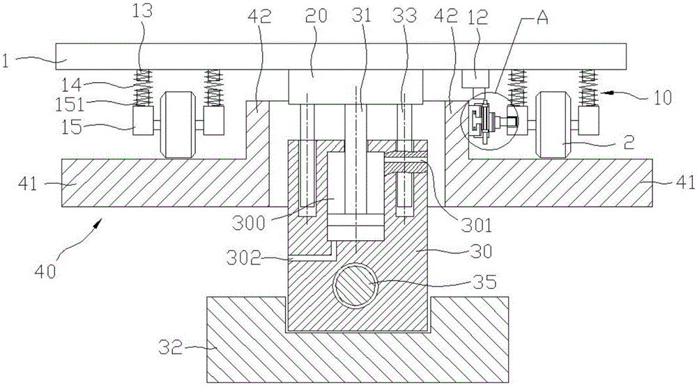
[0033] Such as figure 1 , a raw material handling trolley capable of walking automatically, comprising a material plate 1, a mobile connecting block 20 is fixed in the middle of the bottom surface of the material plate 1, a walking block 30 is arranged below the moving connecting block, and a hydraulic cavity 300 is provided inside the walking block, The top of the hydraulic chamber is provided with a first oil outlet 301, and the bottom of the hydraulic chamber is provided with a second oil outlet 302. The first oil outlet and the second oil outlet are connected to the hydraulic system, and a piston rod 31 is movably inserted in the hydraulic chamber. The rod is vertically arranged, and the top of the piston rod protrudes from the walking block, and the top of the piston rod is fixedly connected with the bottom surface of the mobile connecting block. The guide hole fits; the walking block is slidably fitted on the sliding base 32, and the walking block is provided with a thre...


PUM


Abstract

The invention discloses a raw material carrying trolley capable of automatically traveling. The trolley comprises a material plate. The bottom face of the material plate is connected with at least two traveling wheels through buffering mechanisms. A movable connecting block is fixed to the middle of the bottom face of the material plate. A piston rod is fixed to the middle of the bottom face of the movable connecting block and is inserted in a hydraulic cavity arranged in a traveling block arranged below the material plate. A rotating screw rod is connected to the interior of the traveling block in a threaded mode and connected with a servo motor. Two movable rails are arranged below the material plate and both comprise a transversal part and a limiting part. Adjusting rails are fixed to the outer side walls of the limiting parts and provided with inductors and electromagnets through shifting mechanisms. Limiting grooves matched with control shafts of the electromagnets are formed in the buffering mechanisms, and a detection convex block is fixed to the bottom face of the material plate. A lifting cylinder is connected to the bottom face of the material plate. The raw material carrying trolley has the advantages that materials on the trolley cannot fall out easily, the trolley can automatically ascend and descend and the position can be fixed.

Description

Technical field: [0001] The invention relates to the technical field of chemical equipment, in particular to a material handling trolley capable of walking automatically. Background technique: [0002] In chemical, pharmaceutical and other industries, it is often necessary to transport various raw materials. The existing material handling is generally carried out by manually pushing the trolley, which has low efficiency and high labor intensity. At the same time, the structure of the existing trolley is generally The lower part of the base plate is directly and simply hinged with several walking wheels. When a person pushes the trolley, the ground is uneven, which will cause the trolley to bump, causing the raw materials in the feeding barrel on it to shake out from the center, wasting raw materials, and the structure of this trolley It is non-removable, and if the parts are broken, they need to be replaced as a whole, and the maintenance cost is high. [0003] In addition,...

Claims


Application Information

Patent Timeline
IPC IPC(8): B66F9/065B66F9/075B66F9/22
CPCB66F9/065B66F9/075B66F9/22
Inventor 黄文成
Owner 浙江欧托电气有限公司
Why Eureka
Try Eureka