Die positioning and adjusting structure for double-bent glass forming machine

A positioning adjustment and molding machine technology, applied in glass molding, glass reshaping, glass production, etc., can solve the problems of inability to adjust height, weak applicability, and heavy mold frame, so as to improve production efficiency, ensure quality, Ease of use

Active Publication Date: 2015-11-11
GUANGDONG FUSHAN GLASS MACHINERY
View PDF5 Cites 6 Cited by
  • Summary
  • Abstract
  • Description
  • Claims
  • Application Information

AI Technical Summary

Problems solved by technology

[0002] Double-bend glass forming machines are usually used in the glass bending process. The mold bases used to install molds in existing forming machines are usually fixed on the frame, and the height cannot be flexibly adjusted according to the bending angle of the glass. , so a molding machine can only be used to process a few kinds of glass with different bending angles, which has weak applicability and will have a certain impact on the quality and production efficiency of the glass; some molding machines will detach the mold frame Fixed on the frame, when the height of the formwork needs to be adjusted, the formwork needs to be manually disassembled and fixed again. Since the formwork is usually large and heavy, this method is not easy to implement, and it is also difficult to ensure the level of the formwork, which is likely to affect the quality of the glass

Method used


Image

  • Die positioning and adjusting structure for double-bent glass forming machine
  • Die positioning and adjusting structure for double-bent glass forming machine
  • Die positioning and adjusting structure for double-bent glass forming machine

Examples


Embodiment Construction

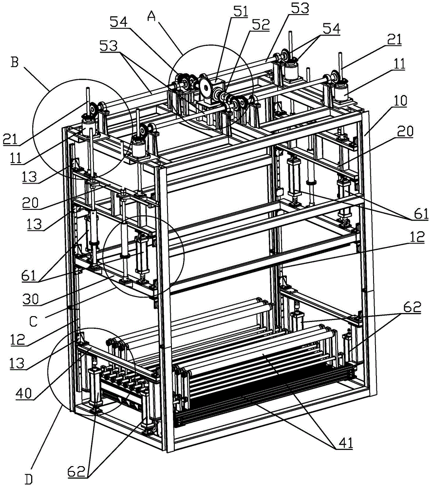
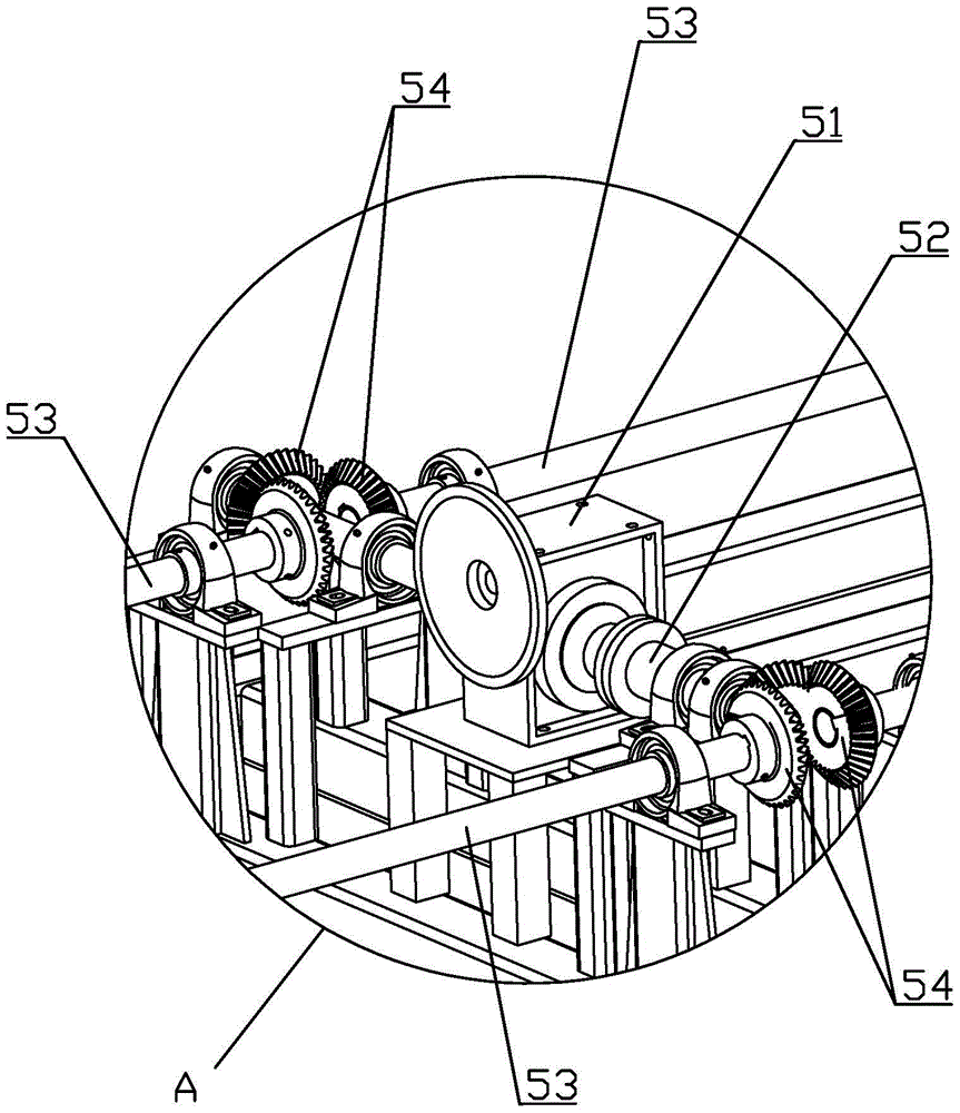
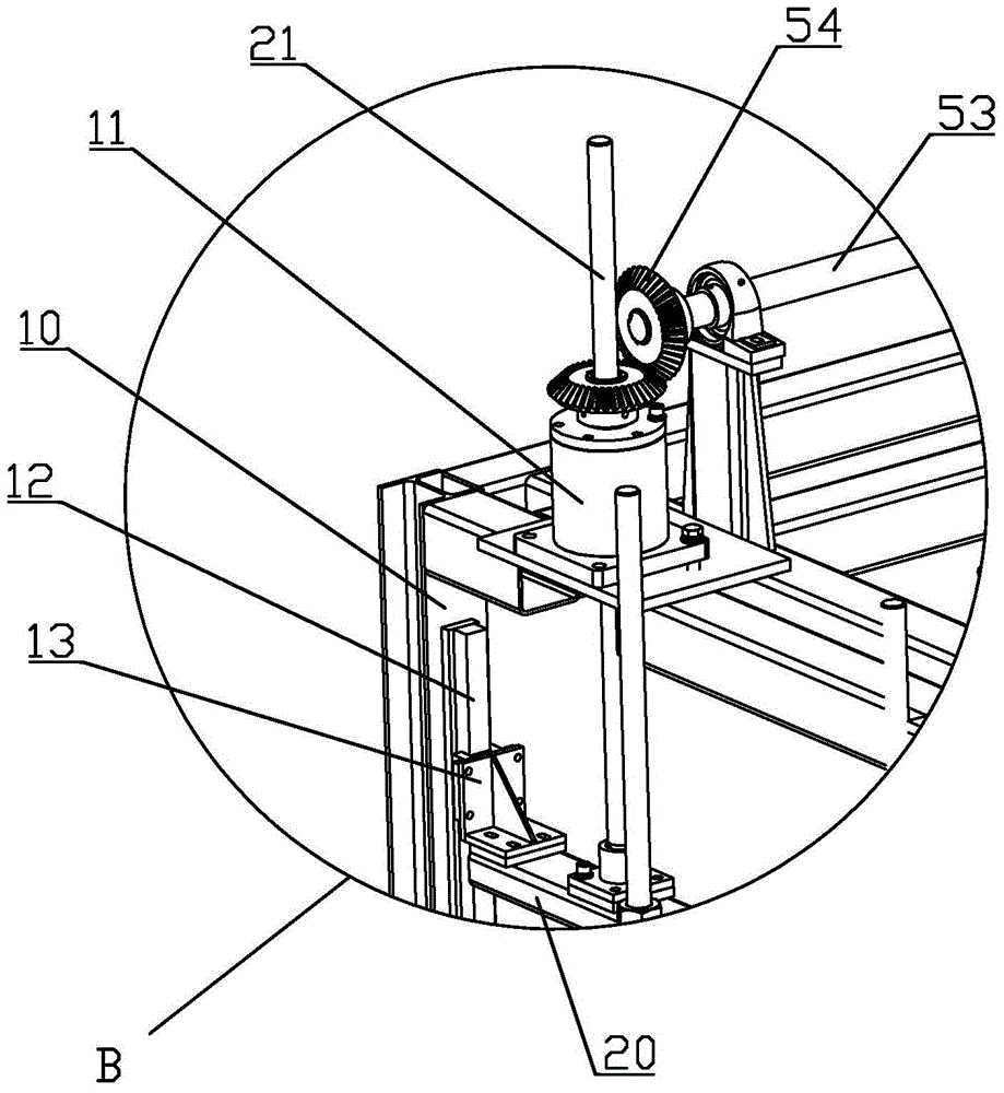
[0021] refer to Figure 1 to Figure 5 , a mold positioning adjustment structure for a double-curved glass forming machine, comprising a frame 10 and two movable beams 20 respectively arranged on the left and right sides of the frame 10, each movable beam 20 is respectively fixed with at least one longitudinal screw rod 21, The frame 10 is provided with a number of sleeves 11 matched with the screw rods 21. These sleeves 11 are driven by a driving device through a transmission mechanism to rotate synchronously, thereby pushing the two movable beams 20 to move up and down synchronously; The formwork 30 is slidably arranged on the frame 10 and is located below the movable beam 20. The left and right sides of the upper formwork 30 are respectively connected with the movable beam 20 through at least one longitudinal first cylinder 61. The first cylinder 61 is used to push the upper The formwork 30 makes it move up and down relative to the movable beam 20; the lower formwork 40 is s...


PUM


Abstract

The invention discloses a die positioning and adjusting structure for a double-bent glass forming machine. The die positioning and adjusting structure comprises a rack, two movable beams, an upper die frame and a lower die frame, wherein the two movable beams are arranged on the left side and the right side of the rack respectively; each movable beam is fixedly provided with at least one longitudinal lead screw. The rack is provided with a plurality of sleeves matched with the lead screws. The sleeves are pushed through a transmission mechanism by means of a drive device and rotate synchronously so as to push the two movable beams to move up and down synchronously. The upper die frame is located below the movable beams. The left side and the right side of the upper die frame are connected with the movable beams through at least one longitudinal first air cylinder. The first air cylinders are used for pushing the upper die frame to move up and down relative to the movable beams. The lower die frame is arranged on the rack in the sliding mode and located below the upper die frame. The lower die frame is connected with the rack through a plurality of longitudinal second air cylinders. The second air cylinders are used for pushing the lower die frame to move up and down relative to the rack. By means of the die positioning and adjusting structure, the height of the upper die frame can be adjusted conveniently and stably, production efficiency can be improved effectively, and the machining quality of glass is guaranteed.

Description

technical field [0001] The invention relates to a glass production equipment, in particular to a double-curved glass forming machine. Background technique [0002] Double-bend glass forming machines are usually used in the glass bending process. The mold bases used to install molds in existing forming machines are usually fixed on the frame, and the height cannot be flexibly adjusted according to the bending angle of the glass. , so a molding machine can only be used to process a small number of glass with different bending angles, which has weak applicability and will have a certain impact on the quality and production efficiency of the glass; some molding machines will detach the mold frame Fixed on the frame, when the height of the formwork needs to be adjusted, the formwork needs to be manually disassembled and re-fixed. Since the formwork is usually large and heavy, this method is not easy to implement, and it is difficult to ensure the level of the formwork, which is l...

Claims


Application Information

Patent Timeline
IPC IPC(8): C03B23/00
CPCY02P40/57
Inventor 李礼开李界平韦玉锐彭辉胜廖满意李景昌
Owner GUANGDONG FUSHAN GLASS MACHINERY
Why Eureka
Try Eureka