
Drain structure

A technology for drainage ditches and ditches, which is applied to drainage structures, waterway systems, water supply devices, etc., and can solve problems such as the inability to improve the efficiency of the drainage ditch structure, the discharge of water into the sewer, and the inability to immediately release a large amount of water storage, etc.

Inactive Publication Date: 2015-11-11
陈正錞
View PDF7 Cites 5 Cited by
  • Summary
  • Abstract
  • Description
  • Claims
  • Application Information

AI Technical Summary

Problems solved by technology

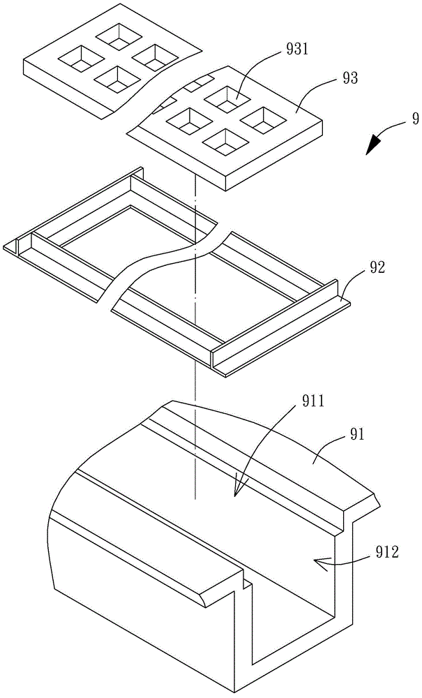
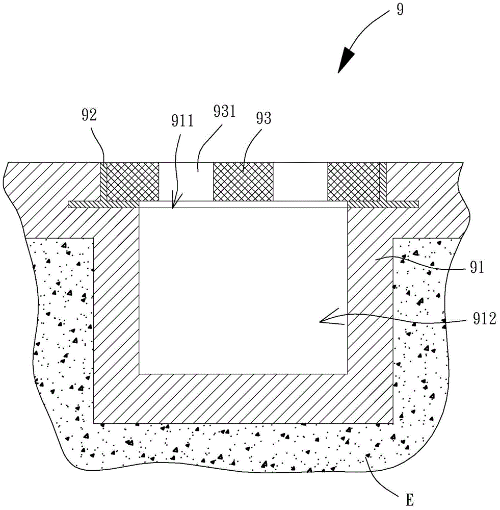
[0004] However, when the rainfall reaches a fixed value at the moment of the heavy rain, the accumulated water and rainwater of the road will be poured into the accommodation space 912 in large quantities continuously, and the accommodation space 912 may not be able to release a large amount of water storage and release the moisture immediately. discharge to the sewer, so that the drainage efficiency of the existing drainage ditch structure 9 is low; And set several formworks around the ditch, inject an appropriate amount of cement into the gaps between the several formworks, wait for the cement to solidify and remove the several formworks to form the ditch body 91, so that the existing drainage system can be constructed. The solidification and molding of the ditch body 91 of the ditch structure 9 will inevitably take a certain amount of man-hours, so that the efficiency of making the existing drainage ditch structure 9 cannot be improved.

Method used


Image

  • Drain structure
  • Drain structure
  • Drain structure

Examples


Embodiment Construction

[0043] In order to make the above and other purposes, features and advantages of the present invention more comprehensible, the preferred embodiments of the present invention are specifically cited below, together with the accompanying drawings, as follows:

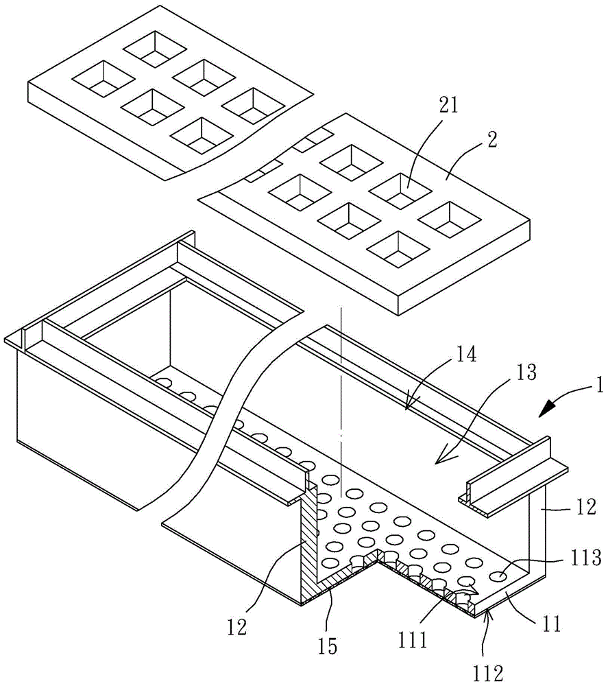
[0044] Please refer to image 3 As shown, this is a three-dimensional exploded view of the drain structure of the first embodiment of the present invention. The drainage ditch structure includes a ditch body 1, and the drainage ditch structure preferably includes a cover body 2, the ditch body 1 and the cover body 2 are combined with each other, and the material of the ditch body 1 can be metal or alloy, etc. , and the groove body 1 is preferably pre-formed in a factory, and the material of the cover body 2 can be metal, alloy or cement, etc., and there is no limitation here.

[0045] The ditch body 1 includes a bottom wall 11, the opposite sides of the bottom wall 11 are respectively connected with a side wall 12, and t...


PUM


Abstract

The present invention discloses a drain structure, comprising a drain body containing a bottom wall. Two sides of the bottom wall are respectively connected with side walls. A housing space is formed by the two bottom walls. The drain body is provided with an opening which is located at one surface of the bottom wall, and the bottom wall is provided with a first surface and a second surface. The bottom wall is provided with a plurality of holes passing through the first surface and the second surface. Because the bottom wall provides a plurality of holes, the extra pipelines for remitting water in the space may be provided so as to improve the drain efficiency of the drain structure.

Description

technical field [0001] The invention relates to a drainage ditch structure, in particular to a drainage ditch structure with good drainage efficiency and convenient construction. Background technique [0002] Taiwan, an island country located in the subtropical latitude zone, is often hit by typhoons in summer, and it often rains an astonishingly large amount of rainwater in an instant, resulting in waterlogging in low-lying areas that cannot be drained, causing people to suffer from the inconvenience of waterlogging. The construction of the drainage ditch can discharge the rainwater through specific pipes, drain the water to the sewer, and further disperse it to the reservoir or the ocean and other areas with a large water-holding space. Therefore, the importance of constructing the drainage ditch it goes without saying. [0003] Please refer to figure 1 As shown, this is a three-dimensional exploded view of the existing drainage ditch structure 9 , which includes a ditch...

Claims


Application Information

Patent Timeline
Patent Type & Authority Applications(China)
IPC IPC(8): E03F5/04
Inventor 陈正錞
Owner 陈正錞
Learn More