Outer decorating layer formwork for conical columns of comprehensive gym and construction method of outer decorating layer formwork

A construction method and decorative layer technology, which are applied to the outer decorative layer formwork of a conical column of a comprehensive gymnasium and its construction field, can solve the problems of high engineering cost, waste of materials, occupation, etc., and achieve satisfactory molding effect, easy assembly and low cost. Effect

Inactive Publication Date: 2015-11-11
CHINA CONSTR SECOND ENG BUREAU LTD +1
View PDF6 Cites 6 Cited by
  • Summary
  • Abstract
  • Description
  • Claims
  • Application Information

AI Technical Summary

Problems solved by technology

[0002] Faced with special-shaped components in tall and large spaces, professional formwork manufacturers are often selected to design and produce shaped formwork, such as shaped steel formwork. The advantages of professional formwork design are more accurate formwork system, stable structure, and more convenient construction, but the project cost is higher. At the same time The stereotyped formwork also has its limitations. When encountering irregular structural components, it cannot be mechanized on the production line. It is very difficult to produce professional formwork and cannot solve the problem. In addition, the production cycle of the stereotyped formwork is long. Occupies a certain period of time, and the non-repeatability of the finalized template will also cause waste of data

Method used


Image

  • Outer decorating layer formwork for conical columns of comprehensive gym and construction method of outer decorating layer formwork
  • Outer decorating layer formwork for conical columns of comprehensive gym and construction method of outer decorating layer formwork
  • Outer decorating layer formwork for conical columns of comprehensive gym and construction method of outer decorating layer formwork

Examples


Embodiment Construction

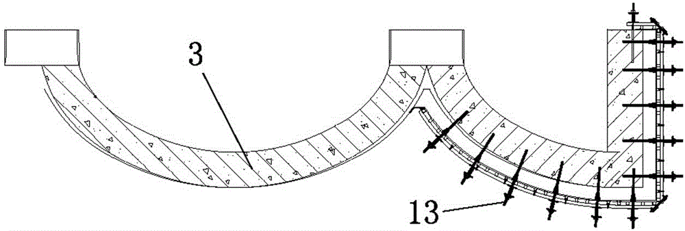
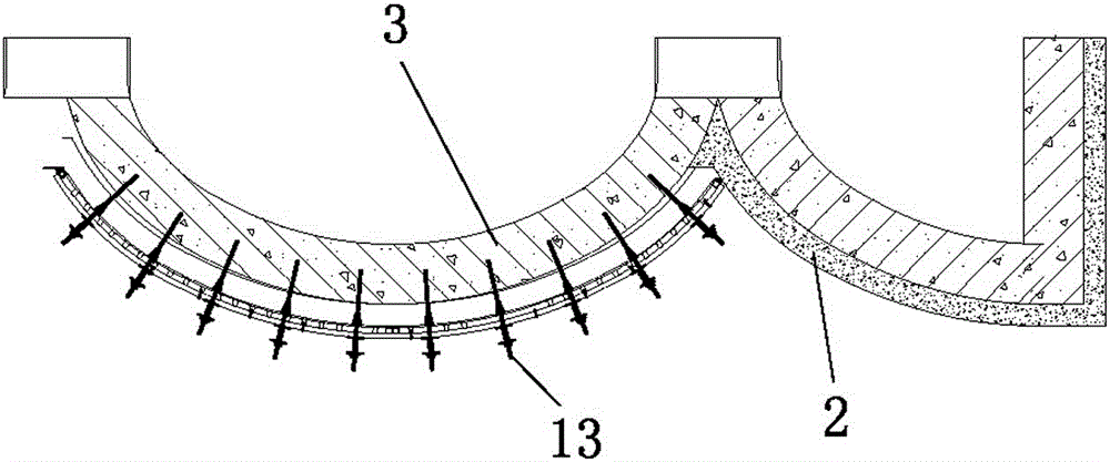
[0030] The specific implementation manners of the present invention will be described below in conjunction with the accompanying drawings.

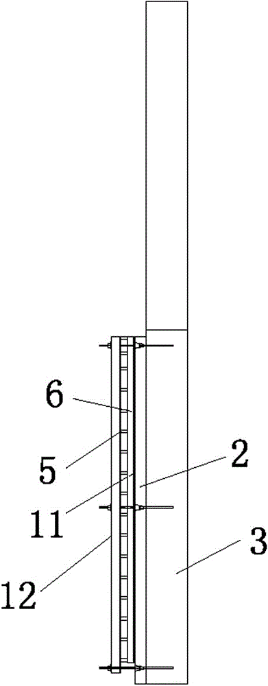
[0031] Such as Figure 1-Figure 2 As shown: the external decorative layer template of the tapered column of the comprehensive gymnasium, the external decorative layer template is located outside the external decorative layer 2, the external decorative layer template includes a cylinder template and a cone template, and the circular top surface of the cylinder template is a cone The bottom surface of the body formwork; the external decorative layer formwork includes: double-layer backboard 11, main keel channel steel back flute 12, secondary keel channel steel 14, several-character beam back flute 6, square steel pipe 5 and pull screw 13, double-layer back The side of the plate 11 facing the decorative layer is lined with plywood, and one end of the pull screw 13 is anchored on the conical concrete column 3, and the main keel channel steel...


PUM


Abstract

The invention relates to a device for casting cast-in-place concrete, in particular to an outer decorating layer formwork for conical columns of a comprehensive gym and a construction method of the outer decorating layer formwork. The outer decorating layer formwork is positioned on the outer side of an outer decorating layer and comprises a face board, back ribs and oppositely-pulling screws, the face board is a bilayer thick wood formwork, a three-ply board is lined on one face, facing the decorating layer, of the face board, and one ends of the oppositely-pulling screws are anchored on conical concrete columns to fix the face board and the back ribs. The construction method includes the following steps: rechecking structural size of cast conical columns; determining a formwork machining detailed drawing; making and assembling the formwork; trepanning for bolts of the formwork; putting the formwork in place for the first time; trepanning structural columns along reserved bolt holes of the formwork; retreating the formwork; implanting sectional screws; putting the formwork for the second time; demounting the formwork. A wood formwork face board and a section steel keel are matched mutually, so that the outer decorating layer formwork is easy to assemble and suitable for structural components variable in shape, and forming effect of the components meets designing requirements under the condition of reasonable and effective reinforcing and supporting.

Description

technical field [0001] The invention relates to a device for pouring in-situ concrete, in particular to a template for the external decorative layer of a tapered column in a comprehensive gymnasium and a construction method thereof. Background technique [0002] Faced with special-shaped components in tall and large spaces, professional formwork manufacturers are often selected to design and produce shaped formwork, such as shaped steel formwork. The advantages of professional formwork design are more accurate formwork system, stable structure, and more convenient construction, but the project cost is higher. At the same time The stereotyped formwork also has its limitations. When encountering irregular structural components, it cannot be mechanized on the production line. It is very difficult to produce professional formwork and cannot solve the problem. In addition, the production cycle of the stereotyped formwork is long. It takes a certain period of time, and the non-rep...

Claims


Application Information

Patent Timeline
Patent Type & Authority Applications(China)
IPC IPC(8): E04G13/02E04G19/00E04G21/00
Inventor 高飞李树成王全逵姜斌刘坤胡杭高李军
Owner CHINA CONSTR SECOND ENG BUREAU LTD
Why Eureka
Try Eureka