
Constant rotating speed automatic control valve assembly of hydraulic motor

A technology for automatic control of valves and motors, applied to servo motor components, fluid pressure actuators, mechanical equipment, etc., can solve the problem of reducing the flow rate of the emulsion supply motor, increasing the flow rate of the emulsion supply motor, and the inability of the emulsion motor to run constantly, etc. problem, to achieve the effect of stable operation, convenient installation and light weight

Inactive Publication Date: 2015-11-11
天津艾浮瑞特科技有限公司
View PDF4 Cites 0 Cited by
  • Summary
  • Abstract
  • Description
  • Claims
  • Application Information

AI Technical Summary

Problems solved by technology

[0003] The present invention solves the problem of "when the emulsion motor is working under the drive of pumping emulsion, when the torque of the motor increases and the pressure of the pipeline increases, the overflow valve begins to overflow, reducing the flow supplied to the emulsion motor, and the emulsion The speed of the motor decreases; when the torque of the emulsion motor decreases, the pressure of the pipeline decreases, the overflow port of the overflow valve is closed, the flow supplied to the emulsion motor increases, and the speed of the motor increases; the difficulty that the emulsion motor cannot run constantly” , a hydraulic motor speed constant automatic control valve assembly is proposed. This system is installed between the pump and the emulsion motor. The pump always supplies a constant flow, which can make the emulsion motor run at a constant speed and constant torque, accurately and smoothly Function

Method used


Image

  • Constant rotating speed automatic control valve assembly of hydraulic motor

Examples


Embodiment Construction

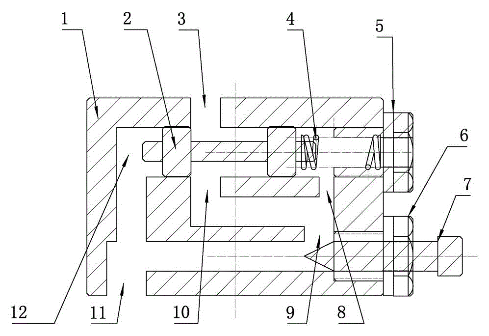
[0016] like figure 1 As shown, the hydraulic motor speed constant automatic control valve assembly described in the embodiment of the present invention includes (1) constant valve block, (2) constant piston, (3) constant oil outlet, (4) constant spring, (5) Spring lock nut, (6) Setting lock nut, (7) Setting adjustment, (8) Feedback oil port, (9) Setting oil port, (10) Adjusting throttling, (11) Oil inlet, (12 ) buffer chamber; characterized in that: the constant valve block (1) is opened to process an oil inlet (11); the oil inlet (11) and the buffer chamber (12) are opened; the setting lock nut ( 6) Connect with the oil inlet (11) and tighten it on the constant valve block (1); the setting adjustment (7) is installed in the setting lock nut (6); the constant piston (2) is installed in parallel on the buffer cavity (12); the constant spring (4) is installed at the end of the constant piston (2); the spring lock nut (5) is screwed on the constant valve block (1); a set of hydr...


PUM


Abstract

The invention discloses a constant rotating speed automatic control valve assembly of a hydraulic motor. The constant rotating speed automatic control valve assembly comprises a constant valve block, a constant piston, a constant oil outlet, a constant spring, a constant lock nut, a setting lock nut, a setting adjustment device, a feedback oil opening, a setting oil opening, an adjustment throttling device, an oil inlet, a buffer cavity and other components. After emulsified liquid passes through the oil inlet to enter the buffer cavity to be buffered, the emulsified liquid passes through the setting adjustment device to enter the setting oil opening. The emulsified liquid enters the adjustment throttling device after being set to achieve needed flow. The emulsified liquid passes through the constant piston through the oil inlet. After the flow of the emulsified liquid is constant through the constant piston, the emulsified liquid is supplied to the emulsified liquid motor through the constant outlet. The emulsified liquid motor runs at constant speed after obtaining the emulsified liquid of the constant flow. The constant rotating speed automatic control valve assembly is not influenced by fluid supply flow or pressure; the flow is kept constant automatically; the emulsified liquid motor can obtain constant pressure and flow; and the function that the assembly runs at constant speed and constant torque and runs precisely and stably is achieved.

Description

technical field [0001] The invention relates to an automatic control valve assembly with constant rotational speed of a hydraulic motor, specifically a constant flow rate is always supplied when pumping emulsion to an emulsion motor whose torque is constantly changing, so as to keep the emulsion motor at a constant speed. , Constant torque operation, precise and smooth operation as a device. Background technique [0002] At present, when the emulsion motor is driven by the pumped emulsion, its operating speed and torque are controlled by the flow valve and the relief valve; when the torque of the motor increases and the pressure of the pipeline increases, the relief valve Start to overflow, reduce the flow supplied to the emulsion motor, and the rotation speed of the emulsion motor decreases; when the torque of the emulsion motor decreases, the pipeline pressure decreases, the overflow port of the overflow valve is closed, the flow supplied to the emulsion motor increases, a...

Claims


Application Information

Patent Timeline
Patent Type & Authority Applications(China)
IPC IPC(8): F15B13/02
CPCF15B13/02
Inventor 肖国刚殷召元李超阚磊张晓虎鲁德丰欧东东刘国利
Owner 天津艾浮瑞特科技有限公司
Learn More