
A Frictionless Fluid Damping Vibration Isolator

A technology of fluid damping and vibration isolator, which is applied in the direction of liquid shock absorber, spring/shock absorber, vibration suppression adjustment, etc. It can solve the problems of large damper size, poor vibration isolation performance, and reduced size of vibration isolator. , to achieve the effect of enhanced damping capacity, wide application range and avoiding friction

Inactive Publication Date: 2018-01-19
SHANGHAI JIAOTONG UNIV
View PDF7 Cites 0 Cited by
  • Summary
  • Abstract
  • Description
  • Claims
  • Application Information

AI Technical Summary

Problems solved by technology

[0006] In view of the problems existing in the above-mentioned prior art, the present invention proposes a frictionless fluid damping vibration isolator. The two cavities are arranged inside and outside, which effectively reduces the size of the vibration isolator and solves the problem of the size of the damper in the prior art. Large, poor vibration isolation problems

Method used


Image

  • A Frictionless Fluid Damping Vibration Isolator
  • A Frictionless Fluid Damping Vibration Isolator
  • A Frictionless Fluid Damping Vibration Isolator

Examples


Embodiment 1

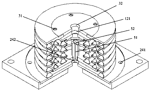
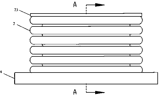
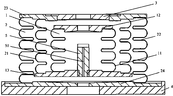
[0049] to combine Figure 1-Figure 9 , this embodiment describes in detail the frictionless fluid damping vibration isolator of the present invention, the sectional view of which is cut off by a quarter is as follows figure 1 shown, as figure 2 Shown is the front view of the frictionless fluid damping vibration isolator of the present invention, as image 3 shown along figure 2A cross-sectional view of the A-A direction, which includes: an inner cavity body 1, an outer cavity body 2, an upper connecting piece 3, a lower connecting piece 4 and a connecting rod 5. The inner cavity body 1 includes: an inner cavity bellows 11, an upper end cover 12 and a lower end cover 13, the upper end of the inner cavity bellows 11 is connected with the upper end cover 12, and the lower end is connected with the inner ring of the lower end cover 13; the outer cavity body 2 includes: The bellows 21 inside the chamber, the bellows 22 outside the outer chamber, the upper flange 23 and the low...

Embodiment 2

[0061] In this embodiment, on the basis of Embodiment 1, a buffer spring 6 is added between the upper end cover 12 and the upper flange 23, which is fixedly connected with the upper end cover 12 and the upper flange 23, and its structural diagram is as follows Figure 10 As shown, the vibration isolator becomes a three-parameter system.

[0062] In different embodiments, the buffer spring can also be replaced by other forms of buffer devices.


PUM


Abstract

The invention discloses a frictionless fluid damping vibration isolator which comprises an inner cavity, an outer cavity, an upper connection piece, a lower connection piece and a through rod. The inner cavity comprises an inner cavity corrugated pipe, an upper end cover and a lower end cover. The inner cavity corrugated pipe, the upper end cover and the lower end cover form the cylindrical inner cavity. The outer cavity comprises an outer cavity inner side corrugated pipe, an outer cavity outer side corrugated pipe, an upper flange and a lower flange. The outer cavity inner side corrugated pipe, the outer cavity outer side corrugated pipe, the upper flange, the lower flange and the lower end cover form the circularly-annular outer cavity. The outer cavity is formed in the outer side of the inner cavity. The upper end cover is located below the upper flange. The upper flange is connected with the upper connection piece. The lower end cover is located above the lower flange. The lower flange is connected with the lower connection piece. The two ends of the through rod are communicated with the inner cavity and the outer cavity. According to the frictionless fluid damping vibration isolator, the two cavies are arranged from inside to outside, the size of the vibration isolator is reduced, and the performance of the vibration isolator is improved.

Description

technical field [0001] The invention relates to the field of micro-vibration control, in particular to a frictionless fluid damping vibration isolator. Background technique [0002] Microvibration is the main factor affecting the pointing accuracy and imaging quality of aircraft and spacecraft. Its main characteristics are small amplitude, wide frequency and difficult control. The micro-vibration displacement is generally on the order of microns or even smaller, but its harm is very significant; the frequency range of micro-vibration ranges from extremely low to thousands of Hz, and the vibration energy in the range of a few Hz to hundreds of Hz is relatively large and difficult to attenuate; Due to the small amplitude of vibration, the propagation mechanism in the mechanical structure is complicated, which makes the performance of traditional vibration reduction methods degrade. [0003] Traditional vibration isolator devices often contain friction, and the damping produce...

Claims


Application Information

Patent Timeline
Patent Type & Authority Patents(China)
IPC IPC(8): F16F9/10F16F15/023
CPCF16F9/10F16F15/023
Inventor 陈燕毫王超新苏金鹏张志谊
Owner SHANGHAI JIAOTONG UNIV
Learn More