
LED projection lamp

A technology of LED floodlights and LED light sources, applied in the field of floodlights, can solve problems such as high voltage of integrated LED lamp beads, unsuitability for mass production, general heat conduction and heat dissipation effects, etc., to avoid glare and glare, assembly High efficiency and good cooling effect

Inactive Publication Date: 2015-11-11
姚耀安
View PDF0 Cites 2 Cited by
  • Summary
  • Abstract
  • Description
  • Claims
  • Application Information

AI Technical Summary

Problems solved by technology

The lamp housing of existing LED floodlights is generally die-cast aluminum, which is heavy, heavy, low flexibility, inconvenient to form, high defective rate in the production process, and general heat conduction and heat dissipation effects
Moreover, the LED light source structure of LED floodlights currently on the market generally adopts integrated LED lamp beads, but the voltage of integrated LED lamp beads is relatively high, which consumes more power, and because the light source is relatively concentrated, it will cause people to feel dazzling.
In addition, the existing substrate and light-transmitting cover are generally connected and fixed by adhesives or screws, which is not easy to install and disassemble, and the assembly efficiency is low, the production efficiency is low, it is not suitable for mass production, and the later maintenance is not convenient enough

Method used


Image

  • LED projection lamp
  • LED projection lamp
  • LED projection lamp

Examples


Embodiment Construction

[0017] It should be understood that the specific embodiments described here are only used to explain the present invention, not to limit the present invention.

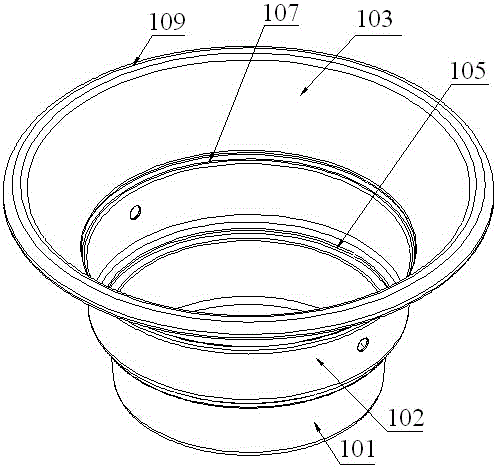
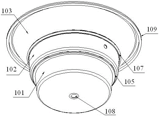
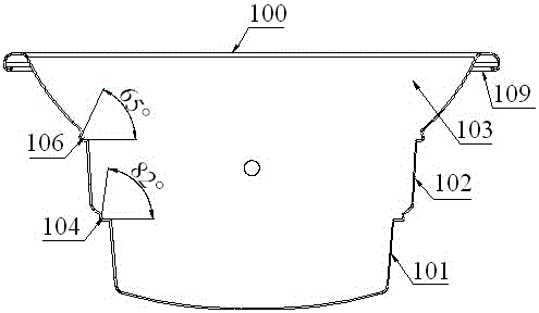
[0018] refer to Figure 1 to Figure 3 , an embodiment of an LED flood light of the present invention is proposed, including a lamp housing 100 formed by spinning an aluminum plate by a drilling machine, an LED light source structure fixed in the lamp housing 100, and a lamp housing 100 And cover the transparent cover on the LED light source structure, and the driving device connected with the LED light source structure.

[0019] Wherein, the light-transmitting cover is made of milky white light-transmitting material, and the white light-transmitting cover makes the light even and soft, and has anti-glare effect.

[0020] Existing lamp housings are generally made of die-cast aluminum, which is relatively heavy, heavy, low flexibility, inconvenient to form, high defective rate in the production process, and general hea...


PUM


Abstract

The invention discloses an LED projection lamp. The LED projection lamp comprises a lamp housing formed by spinning of an aluminum plate through a drilling machine, an LED light source structure clamped in the lamp housing, a light-pervious cover which is clamped in the lamp housing and covers the LED light source structure, and a driving device. The LED light source structure comprises a substrate and SMD LED lamp beads arranged on the substrate. A hollow-cylinder-shaped bottom cavity provided with accommodating space, a middle cavity, and an inverted-circular-truncated-cone-shaped light guiding arc-shaped curved surface formed after an opening in the upper end of the middle cavity inclines and extends outwards, wherein the diameter of the middle cavity is larger than that of the bottom cavity. A first annular clamping groove into which the substrate can be clamped and pressed is formed in the position where the bottom cavity is connected with the inner wall of the middle cavity, and a first included angle is formed on the section of the first annular clamping groove. A second annular clamping groove into which the light-pervious cover can be clamped and pressed is formed in the position where the middle cavity is connected with the inner wall of the light guiding arc-shaped curved surface, and a second included angle is formed on the section of the second annular clamping groove. A wire passing hole is formed in the bottom of the lamp housing, and the lamp housing is integrally formed.

Description

technical field [0001] The invention relates to a floodlight, in particular to an LED floodlight. Background technique [0002] With the continuous breakthrough of LED technology, especially the successful development of high-power and high-efficiency LEDs, it has become a reality to widely use LEDs in various lighting fields, such as LED floodlights, which can be used for tunnel lighting, stage lighting, and field construction lighting , Advertising lighting, exterior wall lighting, road lighting, landscape lighting and storage lighting, etc., are widely used. The lamp housing of the existing LED floodlights is generally die-cast aluminum, which is relatively heavy, heavy in weight, low in flexibility, inconvenient in molding, high in defective rate in the production process, and mediocre in heat conduction and heat dissipation. Moreover, the LED light source structure of LED floodlights currently on the market generally adopts integrated LED lamp beads, but the voltage of...

Claims


Application Information

Patent Timeline
IPC IPC(8): F21S8/00F21V5/00F21V15/02F21V31/00F21V29/507F21V29/89F21V17/10F21Y101/02
CPCF21S8/00F21V5/00F21V15/02F21V17/10F21V31/00
Inventor 姚耀安
Owner 姚耀安
Learn More