
Combined heat pump system adopting trans-critical circulation and absorption heat pump co-production

An absorption heat pump and heat pump system technology, applied in the field of heat pumps, can solve problems such as inability to provide high-temperature heat sources, limited functions, and limited

Active Publication Date: 2015-11-11
ZHEJIANG UNIV
View PDF10 Cites 9 Cited by
  • Summary
  • Abstract
  • Description
  • Claims
  • Application Information

AI Technical Summary

Problems solved by technology

[0005] In order to further improve the utilization rate of waste heat in the transcritical cycle, the combination of compression cycle and absorption cycle can effectively improve the overall COP of the system. The Chinese patent document with application number 201210147756. Composite refrigeration device, which is a closed transcritical compression absorption composite system, can make full use of the high-temperature condensation heat of the transcritical cycle, and greatly improve the efficiency of transcritical refrigeration, but it is limited to the refrigeration function
[0006] Also, for example, the Chinese patent document with application number 200910098013.6 discloses a low-grade energy-driven and mechanical work-driven compound heat pump or refrigeration system, which utilizes high-grade heat and solar energy in the exhaust gas of the compression cycle, and has a low-grade energy heat pump and refrigeration system. A series of advantages, when the gas supply is sufficient, the COP of the system is further improved, but it is limited to the function of a conventional heat pump and cannot provide a high-temperature heat source

Method used


Image

  • Combined heat pump system adopting trans-critical circulation and absorption heat pump co-production

Examples


Embodiment Construction

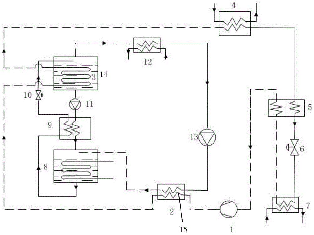
[0039] As shown in FIG. 1 , the combined heat pump system of the transcritical cycle and absorption heat pump in this embodiment includes a transcritical compression subsystem and a second-type absorption heat pump subsystem.

[0040] The steam outlet of the generator 14 of the second type absorption heat pump subsystem is connected with the inlet of the condenser 12, the outlet of the condenser 12 is connected with the inlet of the first solution pump 13, and the outlet of the first solution pump 13 is connected with the inlet of the evaporation channel of the condensing evaporator 2 , the outlet of the evaporation channel of the condensing evaporator 2 is connected with the steam inlet of the absorber 8; the solution outlet of the absorber 8 is connected with the inlet of the first solution channel of the solution heat exchanger 9, and the first solution channel of the solution heat exchanger 9 The outlet is connected with the inlet of the first throttle valve 10, and the out...


PUM


Abstract

The invention discloses a combined heat pump system adopting trans-critical circulation and absorption heat pump co-production. A trans-critical compression subsystem comprises a compression unit, an air cooling unit, a throttling unit and an evaporation unit which are connected through working medium circulation. The air cooling unit is divided into a first heating pipe, a second heating pipe and an air cooling device in the flowing direction of a working medium, wherein the first heating pipe, the second heating pipe and the air cooling device release heat step by step and condense. A heat pump subsystem comprises a generator, a condenser, a first solution pump, a condensing evaporator, an absorber, a solution heat exchanger, a throttling device and a second solution pump. According to the system, by means of reasonable energy coupling, generation heat of the heat pump system comes from condensation heat of the trans-critical compression subsystem completely, a high-temperature heat source with the temperature of above 100 DEG C can be manufactured at the absorber only by inputting a small amount of electric energy, the system has the function of co-production of multiple kinds of energy, the performance coefficient is high when the electric energy is utilized for refrigerating and heating, and the whole system is simple in structure and low in manufacturing cost, and is economical.

Description

technical field [0001] The invention relates to the technical field of heat pumps, and relates to a composite heat pump system in which a transcritical cycle and an absorption heat pump are co-produced. Background technique [0002] The second type of absorption heat pump, that is, heat exchanger, is a device that can recover medium and low temperature waste heat to obtain high temperature useful heat energy. The driving heat source of the second type of absorption heat pump is mostly 60-100°C waste heat discharged in industrial production. When the cooling water temperature is 10-40°C, the temperature of the output hot water or steam is about 100-150°C. Although the performance The coefficient is low (about 0.4-0.5), but because it does not require high-temperature heat input, it has a significant energy-saving effect and has broad application prospects. [0003] With the popularity of energy saving and emission reduction, the transcritical cycle using natural working flui...

Claims


Application Information

Patent Timeline
IPC IPC(8): F25B25/02
Inventor 何一坚王祎李荣蒋云云
Owner ZHEJIANG UNIV
Learn More