Damper apparatus

A damper device and sector gear technology, which is applied to valve devices, transmission devices, gear transmission devices, etc., can solve problems such as abnormal noise

Active Publication Date: 2015-11-11
SANKYO SEIKI MFG CO LTD
View PDF7 Cites 16 Cited by
  • Summary
  • Abstract
  • Description
  • Claims
  • Application Information

AI Technical Summary

Problems solved by technology

Therefore, the sector gear rotates rapidly and the parts come into contact with each other violently, resulting in the problem of abnormal noise.

Method used


Image

  • Damper apparatus
  • Damper apparatus
  • Damper apparatus

Examples


Embodiment Construction

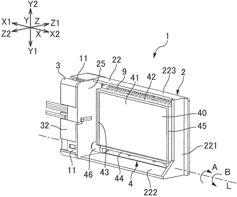
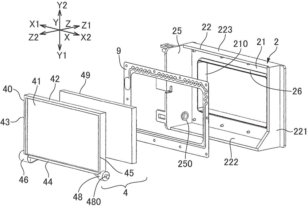
[0063] Hereinafter, a damper device for a refrigerator to which the present invention is applied will be described with reference to the drawings. In the following description, let the rotation center axis of the baffle 4 be L, the direction along the rotation center axis L be the X direction, and the direction facing the opening be the Z direction, and be perpendicular to the X direction and the Z direction. The direction is the Y direction for description. And, let one side of the X direction be X1, the other side of the X direction be X2, one side of the Y direction be Y1, the other side of the Y direction be Y2, one side of the Z direction be Z1, and The other side in the Z direction is described as Z2. In addition, the rotation central axis L is defined as a horizontal direction, the one side Y1 in the Y direction is the lower side in the direction of gravity, and the other side Y2 in the Y direction is described as the upper side in the direction of gravity.

[0064] (...


PUM


Abstract

 Provided is a damper apparatus with which it is possible to suppress abnormal sounds immediately after the locking of gears has been released. Specifically, in a first lock mechanism (81) of the damper apparatus, a first arcuate outer-peripheral part (686) peripherally adjacent to a teeth-missing gear (682) in a drive gear (68) enters a portion of a plurality of teeth (694) in which some teeth are narrowed in the axial direction to restrain a sector gear (69), the plurality of teeth (694) being meshed with the drive gear (68) in the sector gear (69). In the tooth (682c) nearest to the first arcuate outer-peripheral part (686) in the teeth-missing gear (682), the curvature of a first tooth flank (682c1) on the side opposite the first arcuate outer-peripheral part (686) is less than the curvature of a second tooth flank (682c2) on the first arcuate outer peripheral part (686) side, and the tooth (682c) has a curved surface continuous from the first tooth flank (682c1) to the second tooth flank (682c2).

Description

technical field [0001] The present invention relates to a damper device used in cold air passages of refrigerators and the like. Background technique [0002] Regarding damper devices used in cold air passages of refrigerators, etc., there has been proposed a structure in which, for example, a damper is driven by a drive mechanism having a stepping motor and a gear train to open and close an opening formed in a frame (refer to Patent Document 1). In addition, in the damper device described in Patent Document 1, a locking mechanism for maintaining the position of the shutter is provided between the driving gear and the sector gear for the gear train, and the locking mechanism is fitted into the arc-shaped outer peripheral portion of the driving gear. The sector gear is constrained to a portion where the dimension of the axial direction of the second and third teeth from one end in the circumferential direction is narrowed among the plurality of teeth of the sector gear. [...

Claims


Application Information

Patent Timeline
Patent Type & Authority Applications(China)
IPC IPC(8): F25D17/04
CPCF25D17/04F16H19/001F16H35/00F16H2019/008F16H2035/006F25D17/045F16H1/06F16H55/08F16H27/08F16K31/04F16K31/53F25D17/08
Inventor 齐藤俊二林胜彦
Owner SANKYO SEIKI MFG CO LTD
Why Eureka
Try Eureka