
Simple centrifugal dryer

A centrifugal dryer, a simple technology, applied in the direction of drying solid materials, drying solid materials without heating, drying, etc., can solve the problems of material crushing, contamination, material transfer, etc., and achieve the effect of avoiding pollution

Inactive Publication Date: 2015-11-11
苏州赛弗尔机械有限公司
View PDF7 Cites 0 Cited by
  • Summary
  • Abstract
  • Description
  • Claims
  • Application Information

AI Technical Summary

Problems solved by technology

[0004] In the pharmaceutical, chemical and other industries, solid-liquid separation of materials is usually involved. The centrifuges commonly used at present only have the function of solid-liquid separation. Generally, the separated materials still contain a part of water and need to be further dried, which leads to the transfer of materials. and storage issues, there is a risk of contamination
At the same time, the automatic unloading centrifuge widely used at present uses a scraper to scrape the material, which inevitably has the problem of material fragmentation.

Method used


Image

  • Simple centrifugal dryer

Examples


Embodiment Construction

[0012] The present invention will be further described below in conjunction with accompanying drawing.

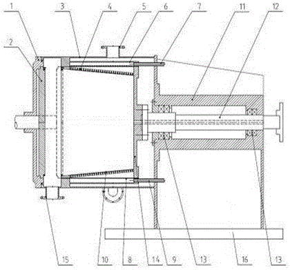
[0013] Simple centrifugal dryer, including machine cover 1, drum front cover 2, casing 3, drum body 4, exhaust port 5, blowback cavity 6, upper air intake pipe 7, drying chamber 8, lower air intake pipe 9, Filter screen 10, bearing 13 box 11, main shaft 12, bearing 13, drum back cover 14, discharge port 15, base 16, characterized in that the bearing 13 box 11 is arranged on the support, the machine cover 1 and the bearing 13 box 11 An organic casing 3 is arranged between them, an exhaust port 5 is arranged above the outer ring of the casing 3, a discharge port 15 is arranged below the outer ring, and a blowback chamber 6 is arranged above the inner wall of the casing 3, and the blowback chamber 6 is arranged above the inner wall of the casing 3, and the blowback The cavity 6 communicates with the upper air intake pipe 7, and a drying cavity 8 is arranged under the inner wal...


PUM


Abstract

The invention relates to a simple centrifugal dryer. The simple centrifugal dryer comprises a dryer cover, a rotary drum front cover, a dryer shell, a rotary drum body, an exhaust port, a blowback cavity, an upper air inlet pipe, a drying cavity, a lower air inlet pipe, a filtering net, a bearing box, a main shaft, bearings, a rotary drum rear cover, a discharge port and a base. The rotary drum body is conical, multiple protrusions are arranged on an outer ring of the rotary drum body, the lower portion of the bearing box is lengthened, and the length of the bearing box is twice the distance between the lower end of the discharge port and the main shaft. As the whole process from feeding, disinfecting, separate dehydrating, drying to discharging is completed in an airtight space, the risk that materials are contaminated in the transferring process is avoided; air is adopted for blowback to discharge the materials, a mechanical scraper is omitted, and therefore particle breakage is avoided.

Description

technical field [0001] The invention relates to the field of drying equipment, in particular to a simple centrifugal dryer. Background technique [0002] Drying equipment is also called dryer and dryer. The equipment used for drying operation, the moisture in the material (generally refers to water or other volatile liquid components) is vaporized and escaped by heating to obtain a solid material with a specified moisture content. The purpose of drying is to meet the needs of material use or further processing. For example, drying wood before making wooden molds and woodware can prevent product deformation, and drying ceramic blanks before calcination can prevent cracking of finished products. In addition, the dried materials are also convenient for transportation and storage, such as drying the harvested grains below a certain moisture content to prevent mildew. Since natural drying is far from meeting the needs of production development, various mechanized dryers are mo...

Claims


Application Information

Patent Timeline
IPC IPC(8): F26B5/08F26B25/00
Inventor 石政和林阿坤
Owner 苏州赛弗尔机械有限公司
Learn More