
Cable stress measuring device based on fiber grating sensing technology
A fiber grating and stress measurement technology, applied in the direction of measuring devices, tension measurement, force measurement, etc., can solve the problems of large measurement results, uncertain relationship between cable force, inconvenient installation, etc., and achieve good electrical insulation performance, small transmission loss, The effect of easy disassembly and assembly
Patent Information
- Authority / Receiving Office
- CN · China
- Patent Type
- Applications(China)
- Current Assignee / Owner
- Publication Date
- 2015-11-11
- Estimated Expiration
- Not applicable · inactive patent
Smart Images
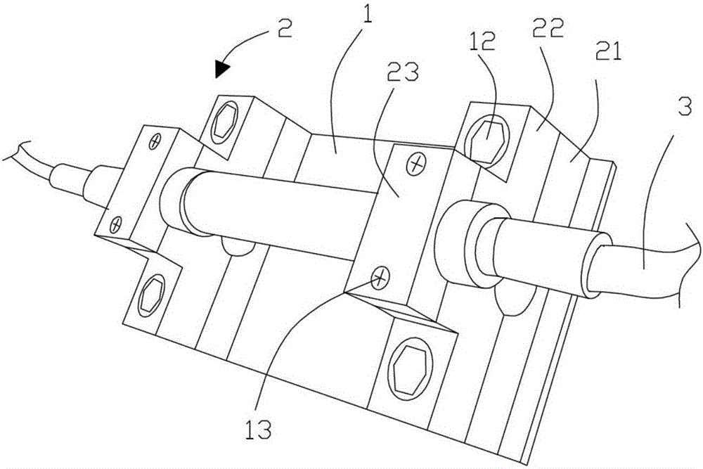
Figure 1 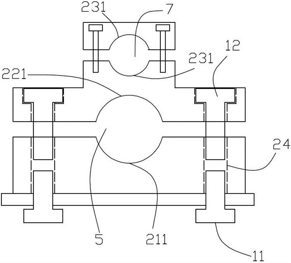
Figure 2
Abstract
Description
technical field
[0001] The invention relates to the field of detection devices, in particular to a cable body stress measurement device based on fiber grating sensing technology. Background technique
[0002] At present, the commonly used cable force measurement methods in engineering include: vibration frequency method, oil pressure gauge reading method, pressure sensor method and three-point bending method.
[0003] The frequency method has many shortcomings. When using this method to test the cable force, we usually define the two ends of the cable as hinged supports or fixed supports. However, in the case of multi-point elastic support boundaries, The relationship between the magnitude of the cable force and the frequency is uncertain. At the same time, there are still some difficulties in picking up and determining the self-vibration frequency of the cable.
[0004] The oil pressure gauge reading method is only suitable for measuring the active cable force of the stru...
Examples
Embodiment 1
[0025] refer to figure 1 and figure 2 As shown, a cable body stress measurement device based on fiber grating sensing technology includes a positioning base plate 1, and two clamping parts 2 are arranged symmetrically on the surface of the positioning base plate. Clamping block 22 and upper pressing block 23, both ends of the lower clamping block are provided with threaded through holes 24 that run through the surface and bottom of the lower clamping block, the positioning base plate is locked with the threaded through hole by the first screw 11, and the lower clamping block There is a first arc-shaped groove 211 in the middle of the surface, and a second arc-shaped groove 221 symmetrical to the first arc-shaped groove 211 is arranged in the middle of the bottom of the upper clamping block. The first arc-shaped groove matches the second arc-shaped groove. The groove clamps the cable body, and the two ends of the upper clamping block are locked with the threaded through hole ...
Embodiment 2
[0034] The difference between embodiment two and embodiment one is that the fiber grating sensor is a bidirectional strain fiber grating sensor, and the strain measurement range of the fiber grating sensor is -2000με—+3000με. After using the bidirectional strain fiber grating sensor, the cable structure that has been in operation can be Whether the cable force is increased (expressed as positive strain) or decreased (expressed as negative strain) under the action of external factors, the data can be transmitted to the data through the bidirectional strain fiber grating sensor In the collector, it can be used in a wide range.