Automatic steel ball detection equipment based on eddy current

A detection equipment, eddy current technology, applied in measuring devices, material analysis through electromagnetic means, instruments, etc., can solve the problems of high use and maintenance costs, high cost, short service life, etc., and achieve low maintenance costs and detection efficiency and the effect of improved detection accuracy and simple and reasonable structure

Inactive Publication Date: 2015-11-11
NINGBO BAIJIABAI MEASUREMENT & CONTROL EQUIP
View PDF11 Cites 9 Cited by
  • Summary
  • Abstract
  • Description
  • Claims
  • Application Information

AI Technical Summary

Problems solved by technology

At present, there are few equipments for internal flaw detection of steel balls at home and abroad. Only the Czech AVIKO company has developed steel ball detection equipment, which uses the cooperation of eddy current probes and meridian expansion wheels for internal flaw detection of steel balls. The detection accuracy of flaw detection is high, but because the radial wheel is made of hard alloy, the tight friction between the radial wheel and the steel ball will wear the surface of the steel ball when the steel ball is unfolded, so this test can only detect semi-finished balls, and it will increase the number of steel balls. The technological process of the production enterprise, and the meridian wheel itself is also a consumable part, with a short service life and high cost, resulting in high use and maintenance costs for the steel ball production enterprise. Perform flaw detection
[0005] Another problem is how to improve the detection efficiency on the premise of ensuring the detection accuracy of steel balls. Taking domestic medium-sized steel ball manufacturers as an example, the annual production of steel balls is measured in hundreds of millions of pieces, so the steel ball detection equipment is also required Must have high detection efficiency

Method used


Image

  • Automatic steel ball detection equipment based on eddy current
  • Automatic steel ball detection equipment based on eddy current
  • Automatic steel ball detection equipment based on eddy current

Examples


Embodiment Construction

[0022] Below in conjunction with accompanying drawing and embodiment of description, the specific embodiment of the present invention is described in further detail:

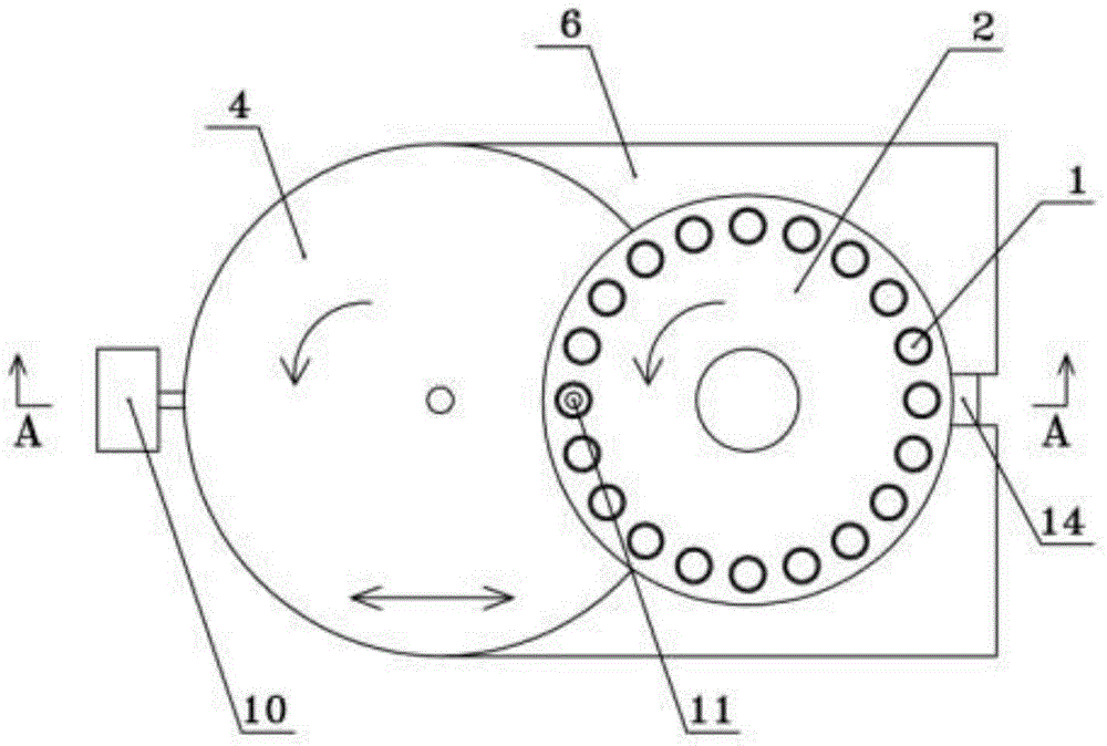
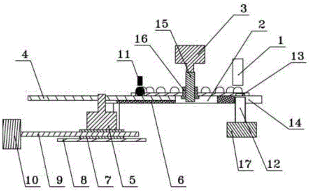
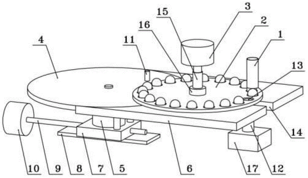
[0023] refer to Figure 1 to Figure 4 The shown automatic steel ball detection equipment based on eddy current includes a feed mechanism 1, a feed turntable 2, a first drive device 3, an unfolding turntable 4, a second drive device 5, a tray 6, a slider 7, and a guide rail 8. Screw rod 9, third driving device 10, eddy current probe 11, eddy current detector (not shown) and discharge mechanism 12.

[0024] The feed turntable 2 is provided with several detection chambers 13, the feed mechanism 1 is connected to the detection chamber 13, the first driving device 3 drives the feed turntable 2 to rotate, the unfolding turntable 4 and the tray 6 are arranged below the feed turntable 2, when When the steel ball to be inspected is located in the detection cavity 13 of the feed turntable 2, the lower end of the steel ba...


PUM


Abstract

The invention relates to automatic steel ball detection equipment based on eddy current. The automatic steel ball detection equipment comprises a feeding mechanism, a feeding rotating disc, a first driving device, an unfolded rotating disc, a second driving device, a tray, a sliding block, a guide rail, a lead screw, a third driving device, an eddy current probe, an eddy current detector and a discharging mechanism. A plurality of detection cavities are arranged on the feeding rotating disc. The feeding mechanism is connected with the detection cavities. The first driving device drives the feeding rotating disc to rotate. The second driving device drives the unfolded rotating disc to rotate. The second driving device and the tray are fixedly arranged on the sliding block. The sliding block is arranged on the guide rail in a sliding mode. The lead screw is in screw-thread fit with the sliding block. The third driving device drives the lead screw to rotate. The eddy current probe is connected with the eddy current detector. According to the automatic steel ball detection equipment, the detection efficiency and the detection precision are greatly improved, the structure is simple and reasonable, no expensive quick-wear parts are adopted, the maintenance cost is low, and the automatic steel ball detection equipment can be used as an upgrade substitute product for steel ball detection equipment based on machine vision.

Description

technical field [0001] The invention relates to the technical field of steel ball detection equipment, in particular to an automatic steel ball detection equipment based on eddy current detection. Background technique [0002] High-end steel balls, such as high-precision steel balls required by industries such as high-speed rail, aviation, high-end automobiles and high-precision CNC equipment, are still monopolized by countries with advanced production technology and testing technology. Through continuous technological innovation, domestic steel ball production enterprises now have the technical strength to produce high-end steel balls. However, they are limited by relatively backward steel ball testing equipment and technology, and cannot participate in the competition of high-end steel balls in the international market. middle. [0003] Steel ball detection includes steel ball surface defect detection and steel ball internal compactness flaw detection, steel ball surface ...

Claims


Application Information

Patent Timeline
Patent Type & Authority Applications(China)
IPC IPC(8): G01N27/90G01N27/9093
CPCG01N27/90
Inventor 李方
Owner NINGBO BAIJIABAI MEASUREMENT & CONTROL EQUIP
Why Eureka
Try Eureka