Emission wave beam nulling widening method based on orthogonal projection

A technology of transmitting beams and zero-notch broadening, which is applied in radio wave measurement systems, instruments, etc., and can solve the problem of inability to form wide zero-notches

Inactive Publication Date: 2015-11-11
UNIV OF ELECTRONICS SCI & TECH OF CHINA
View PDF3 Cites 6 Cited by
  • Summary
  • Abstract
  • Description
  • Claims
  • Application Information

AI Technical Summary

Problems solved by technology

[0017] Aiming at the defect that the traditional orthogonal projection algorithm cannot form wide nulls, the present invention proposes a method for widening nulls of transmitting beams based on orthogonal projections

Method used


Image

  • Emission wave beam nulling widening method based on orthogonal projection
  • Emission wave beam nulling widening method based on orthogonal projection
  • Emission wave beam nulling widening method based on orthogonal projection

Examples


Embodiment Construction

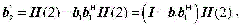
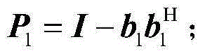
[0035] The present invention aims to find out the left and right intervals of each zero trap, and reconstruct the steering vector matrix to reduce the amount of data. Through the Gram-Schmidt orthogonalization method, the inverse calculation of the matrix is ​​avoided, so that the wide zero-notch beam pattern can be obtained quickly, further reducing the amount of calculation, and improving the system performance.

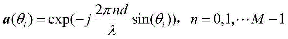
[0036] Since the zeroing direction of the transmitting end is known, so at θ 1 ,θ 2 ,…,θ K K zero-setting directions can be directly passed through the steering vector matrix A=[a(θ 1 )a(θ 2 )…a(θ K )] to express the subspace of the zeroing direction, and then project the steering vector of the transmitting beam on the orthogonal complement space of the direction to be zeroed, and the optimal weight can be obtained

[0037] w o p t = P A ...


PUM


Abstract

The invention discloses an emission wave beam nulling widening method based on orthogonal projection, and relates to the digital array radar emission wave beam nulling widening technology. The method utilizes a reconstruction zero setting vector matrix, and data volume is reduced greatly. In addition, in order to avoid matrix inversion operation, a Gram-Schmidt orthogonalization (GSO) thought is introduced, and a recursion method is employed to carry out deducing of orthogonal complementary space. The provided method achieves emission wave beam nulling widening rapidly and flexibly under a condition that an emission wave beam pointing direction, a zero setting direction and a nulling width are known and the anti-interference performance of the system is enhanced.

Description

technical field [0001] The invention relates to a digital array radar transmission beam nulling widening technology, in particular to a transmission beam nulling widening method based on orthogonal projection. Background technique [0002] Beamforming methods can be classified into transmit beamforming and receive beamforming. Transmit beamforming mainly includes the following technical points: 1) The transmit beam forms a narrow main beam in the desired direction to enhance the desired signal, and at the same time forms a null in the undesired direction to suppress the transmit power in the undesired direction or offset; 2) Some kind of adaptive algorithm and digital signal processing technology need to be used to calculate the weight loaded on each array element, and the weight can be updated by software. Transmit beamforming is also called transmit pattern design. Usually, transmit pattern design does not depend on received data and is designed offline. However, prior in...

Claims


Application Information

Patent Timeline
Patent Type & Authority Applications(China)
IPC IPC(8): G01S7/02
CPCG01S7/02
Inventor 谢菊兰吴若增李昕亚邓金花何子述
Owner UNIV OF ELECTRONICS SCI & TECH OF CHINA
Why Eureka
Try Eureka