
Beam forming method of mimo tracking radar based on radio frequency stealth

A technology for tracking radar and transmitting beams, which is applied in the field of transmitting beamforming based on radio frequency stealth considerations, can solve the problems of increasing difficulty, not involving radar radio frequency stealth performance, etc., and achieve the effect of improving radio frequency stealth performance.

Inactive Publication Date: 2017-09-26
UNIV OF ELECTRONICS SCI & TECH OF CHINA
View PDF2 Cites 0 Cited by
  • Summary
  • Abstract
  • Description
  • Claims
  • Application Information

AI Technical Summary

Problems solved by technology

At present, there are two main methods for MIMO radar transmit beamforming: the first is to design the covariance matrix of the signal first, and then synthesize the transmit signal with specific partial correlations through the obtained covariance matrix (Fuhrmann D R, San Antonio G. Transmit beamforming for MIMO radar systems using signal cross-correlation[J].IEEE Transactions on Aerospace and Electronic Systems,2008,44(1):171-186; Sajid Ahmed,John S.Thompson,Yvan R.Petillot et al.Unconstrained Synthesis of Covariance Matrix for MIMO Radar Transmit Beampattern[J], IEEE Transactions on Signal Processing, 2011,59(8):3837-3849); this method couples the air domain (beam) and time domain (signal) together, greatly increasing design difficulty
The second is to regard the transmitted signal as a weighted sum of a given set of orthogonal waveforms (John Lipor, Sajid Ahmed and Mohamed-Slim Alouini. Fourier-Based Transmit Beampattern Design Using MIMO Radar[J]. IEEE Transactions OnSignal Processing, 2014,62(9):2226-2235; Sajid Ahmed and Mohamed-SlimAlouini.MIMO Radar Transmit Beampattern Design Without Synthesising the Covariance Matrix[J].IEEE Transactions On Signal Processing,2014,62(9):2278-2289), through Design the weighting matrix to obtain the desired method diagram; in this method, it is not necessary to know the specific form of the waveform, as long as the waveforms are orthogonal, but the main purpose of this method is to improve the detection performance of the target, and does not involve radar radio frequency stealth performance

Method used


Image

  • Beam forming method of mimo tracking radar based on radio frequency stealth
  • Beam forming method of mimo tracking radar based on radio frequency stealth
  • Beam forming method of mimo tracking radar based on radio frequency stealth

Examples


Embodiment Construction

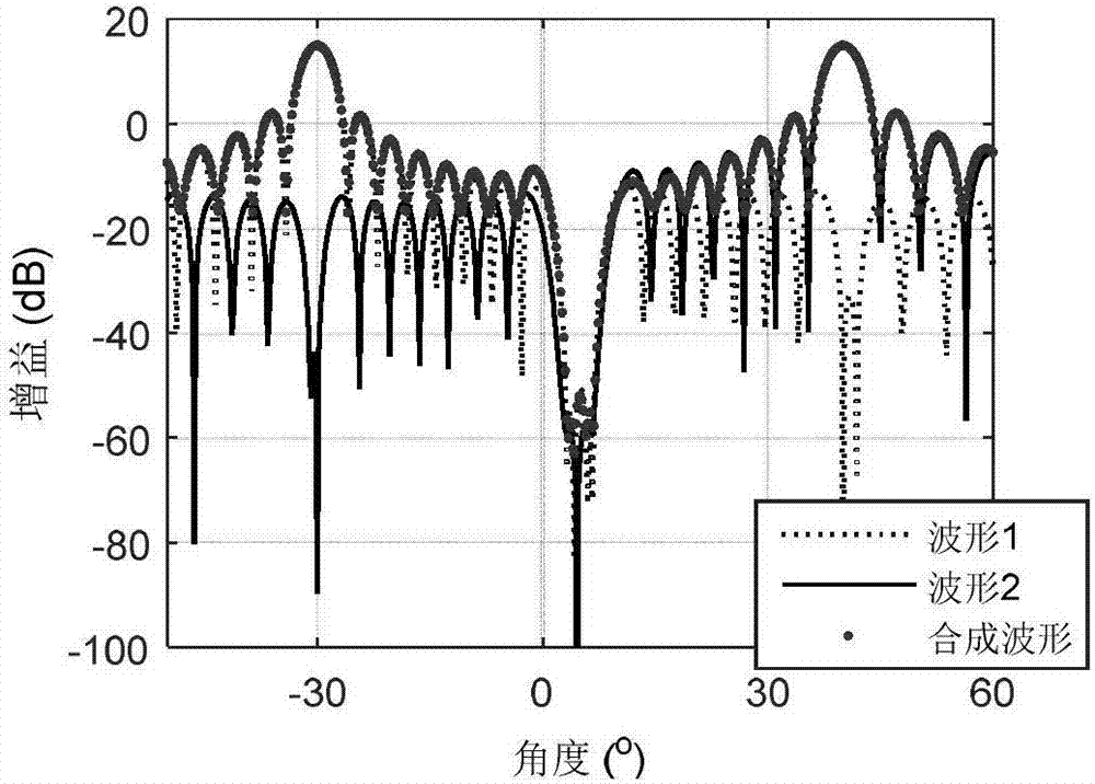
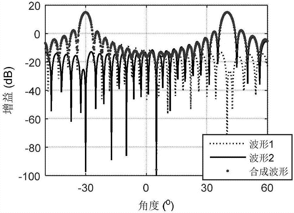
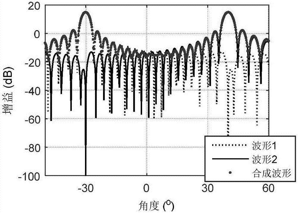
[0065] By comparing the MIMO radar transmitting beamforming method based on radio frequency stealth with the beamforming without null-sag broadening and the intercept probability of the beam-forming method without null-sag, it is shown that the method of the present invention can maintain radar detection performance Improve the radio frequency stealth performance of the radar.

[0066] For MIMO tracking radar, let T OT / T I = 1, since only a single intercept receiver is considered, and it is assumed that the position of the intercept receiver is generally known and not in the main lobe, so the MFD can be set I =1. Therefore, formula (7) can be simplified as

[0067]

[0068] Assume that the radar array is a uniform linear array, the number of array elements is 32, and the spacing between array elements is half a wavelength. The radar tracks two targets at the same time, assuming that there is an intercept receiver, the position information of the target and the intercep...


PUM


Abstract

The invention provides a radio-frequency stealth-based MIMO tracking radar transmit beam forming method, which belongs to the technical field of communication radar. The present invention forms a directional beam in the direction of the target and a wide null limit in the direction of the intercepting receiver by designing the weighting coefficient of the orthogonal transmission waveform; and adopts the discrete prolate sphere sequence method to form a wide beam in the direction of the target to simultaneously detect a wider beam sector; finally, according to the beam gain in each target direction, the minimum power required to make the radar radiate to detect the target. The invention improves the radio frequency stealth performance of the MIMO radar through zero trapping and radiation power control, so that while the MIMO radar ensures the multi-target tracking and detection performance, its radio frequency stealth performance is also improved.

Description

technical field [0001] The invention belongs to the technical field of communication radar, and in particular relates to a transmit beam forming method based on radio frequency stealth considerations in MIMO radar tracking mode. Background technique [0002] On the premise of ensuring the performance of the radar mission, reducing the transmission power of the radar is one of the main means to improve its radio frequency stealth performance. When working, the radar can obtain the location information of the intercepting receiver through cooperative sensors. If the energy distribution of the radar radiation can be made as small as possible in the direction of the intercepting receiver, the probability of the radar being intercepted can be reduced as much as possible. When considering the error in the position of the intercepting receiver obtained by the radar, in order to better improve the radio frequency stealth performance, it is necessary to make the radar transmit beam f...

Claims


Application Information

Patent Timeline
Patent Type & Authority Patents(China)
IPC IPC(8): G01S7/282
CPCG01S7/282
Inventor 程婷武俊青杨少委张宇轩张洁
Owner UNIV OF ELECTRONICS SCI & TECH OF CHINA
Learn More