Large target surface continuous zooming optical system

An optical system and large target surface technology, applied in the field of large target continuous zoom optical system, can solve the problems of low resolution, small target surface, high-definition CCD or CMOS camera can not be matched, etc., to achieve a wide range of applications and improve the recognition ability Effect

Active Publication Date: 2015-11-11
凯迈(洛阳)测控有限公司
View PDF6 Cites 2 Cited by
  • Summary
  • Abstract
  • Description
  • Claims
  • Application Information

AI Technical Summary

Problems solved by technology

[0003] The purpose of the present invention is to provide a continuous zoom optical system with a large target surface to solve the problem that the existing system has a small target surface, low resolution, and cannot be matched with a high-definition CCD or CMOS camera

Method used


Image

  • Large target surface continuous zooming optical system
  • Large target surface continuous zooming optical system
  • Large target surface continuous zooming optical system

Examples


Embodiment Construction

[0023] The present invention will be described in further detail below in conjunction with the accompanying drawings.

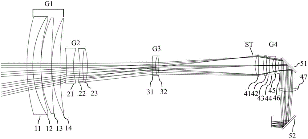
[0024] like figure 1 In the continuous zoom optical system with large target surface shown, the light is incident into the optical system from the object side, and along the direction of light propagation, the optical system includes the front fixed group G1 with positive power and the fixed group G1 with negative power. Zoom group G2, compensation group G3 with negative focal power, and rear fixation group G4 with positive focal power. A diaphragm ST is provided on the optical path between the compensation group G3 and the rear fixing group G4.

[0025] The front fixed group is composed of four lenses, which are respectively: the first front fixed lens is a negative lens 11 with a concave surface facing the diaphragm, the second front fixed lens is a positive lens 12 with a concave surface facing the diaphragm, and the third front fixed lens is a concave le...


PUM


Abstract

The invention relates to a large target surface continuous zooming optical system, comprising a front fixed group, the focal power of which is positive, a zooming group, the focal power of which is negative, a compensation group, the focal power is negative and a rear fixed group, the focal power of which is positive; and the zooming of the optical system is realized through the corresponding movement of the zooming group and the compensation group. The target surface of the continues zooming optical system is 1 inch, which is applicable to a high definition CCD or a CMOS, wherein the pixels are 1920*1082, the size of the pixel is 7.4 Mum, and the target surface is 1 inch. The continues zooming optical system is also applicable to the CCD or the CMOS camera, wherein the pixels are 1920*1080, the size of the pixel is 5.5 Mum, and the target surface is 2/3 inch. The focal length of the optical system is 35mm-700mm, greatly improves the long distance observation capability, adapts to the skyborne optoelectronic system, can detect a long-distance object, improves the capabilities of observing, striking and long-distance identification, and has a wide application range.

Description

technical field [0001] The invention relates to a visible light optical system of an airborne photoelectric device, in particular to a large target surface continuous zoom optical system. Background technique [0002] The load of the carrier aircraft is inversely proportional to its flight range. Therefore, the visible light optical system suitable for airborne optoelectronic equipment requires its small size and light weight; for high-altitude reconnaissance and strike systems, the optical system is required to be able to The target search can also do small-scale target tracking and identification. Therefore, the optical system should have the characteristics of long focal length, large zoom ratio and high resolution. In the future, airborne optoelectronic equipment will gradually replace the standard-definition equipment by high-definition. The target surface of high-definition CCD or CMOS imaging devices is 2 / 3 inch or more than 1 inch, but the existing optical system ha...

Claims


Application Information

Patent Timeline
Patent Type & Authority Applications(China)
IPC IPC(8): G02B15/17
Inventor 吴海清田海霞崔莉赵新亮李同海
Owner 凯迈(洛阳)测控有限公司
Why Eureka
Try Eureka