Anti-aliasing rotation dislocation array antenna

An array antenna, rotation dislocation technology, applied in the direction of antenna, antenna array, individually powered antenna array, etc., can solve the problems of low sensitivity and serious aliasing problem

Active Publication Date: 2021-05-07
SHANGHAI SPACEFLIGHT INST OF TT&C & TELECOMM
View PDF11 Cites 1 Cited by
  • Summary
  • Abstract
  • Description
  • Claims
  • Application Information

AI Technical Summary

Problems solved by technology

[0004] The technical purpose of the present invention is to provide an anti-aliasing rotating d

Method used


Image

  • Anti-aliasing rotation dislocation array antenna
  • Anti-aliasing rotation dislocation array antenna
  • Anti-aliasing rotation dislocation array antenna

Examples


Embodiment 1

[0034] see figure 1 , this embodiment provides an anti-aliasing rotational misalignment array antenna, and how it is obtained will now be described in detail.

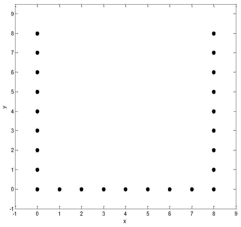
[0035] see image 3 , in this embodiment, firstly, several antenna units need to be placed in a coordinate system according to a U-shaped layout array, wherein, the coordinate system is only for intuitively seeing the positional relationship of the antenna units, and has nothing to do with practical applications. The spacing in the coordinate system 1 stands for 1*Δu. Specifically, the distance between several adjacent antenna units is Δu, and the U-shaped array includes three sides composed of antenna units, each side is a straight line and two adjacent sides are perpendicular to each other. The U-shaped array is now divided into a first sub-array antenna, a second sub-array antenna, and a third sub-array antenna, wherein the first sub-array antenna is the bottom side of the U-shaped array, which includes N antenna ...


PUM


Abstract

The invention discloses an anti-aliasing rotation dislocation array antenna, which is characterized in that a first sub-array antenna, a second sub-array antenna and a third sub-array antenna are arranged in a U shape, the second sub-array antenna is parallel to the third sub-array antenna, the first sub-array antenna is perpendicular to the second sub-array antenna and the third sub-array antenna, the first array antenna and the positive direction of the x axis of the coordinate system form an angle of 45 degrees, and the first array antenna and the positive direction of the y axis of the coordinate system form an angle of 45 degrees; the fourth sub-array antenna is parallel to the first sub-array antenna; the distances between the antenna units at the two ends of the fourth sub-array antenna and the antenna unit at the end, which is away from the first sub-array antenna, of the second sub-array antenna and the antenna unit at the end, which is away from the first sub-array antenna, of the third sub-array antenna are both the value shown in the description. According to the invention, the number of sampling points of a visibility function is increased, and the detection sensitivity of the system is improved while the detection non-aliasing area is enlarged, so that the inversion imaging area is widened, and the clarity of the inversion image is improved.

Description

technical field [0001] The invention belongs to the field of microwave remote sensing with a passive synthetic aperture system, and in particular relates to an anti-aliasing rotating dislocation array antenna. Background technique [0002] Synthetic aperture microwave radiation detection is a passive microwave remote sensing technology that obtains target characteristics by receiving microwave energy radiated from the observed scene. It is a large-aperture antenna equivalent to real-aperture detection with multiple small-element antennas according to a certain array layout (T-type, Y-type, O-type, etc.) to obtain high spatial resolution that cannot be achieved due to the size limit of the real-aperture antenna. . Through interferometry between every two small element antennas, the spatial frequency domain of the radiant brightness temperature distribution in the field of view is sampled to obtain the visibility function, and then the brightness temperature image is reconstr...

Claims


Application Information

Patent Timeline
IPC IPC(8): H01Q21/00H01Q21/08
CPCH01Q21/00H01Q21/08H01Q21/061
Inventor 栾英宏吕利清李秀伟孙彦龙刘瑞冯剑锋李宁杰李丹陈雄
Owner SHANGHAI SPACEFLIGHT INST OF TT&C & TELECOMM
Why Eureka
Try Eureka