
Liquid crystal display panel

A liquid crystal display panel and display area technology, which is applied in nonlinear optics, instruments, optics, etc., can solve the problems of destroying the adhesiveness of the frame glue, difficult to control the stop line, affecting the gap between the first substrate and the second substrate, etc. Guarantees tightness and avoids uneven color effects

Active Publication Date: 2015-11-11
TCL CHINA STAR OPTOELECTRONICS TECH CO LTD +1
View PDF4 Cites 11 Cited by
  • Summary
  • Abstract
  • Description
  • Claims
  • Application Information

AI Technical Summary

Problems solved by technology

In recent years, due to the development trend of narrow bezels of LCD panels, it is necessary to design the distance between the effective display area of ​​the LCD panel, that is, the AA area and the frame rubber area, to be relatively close, which leads to a problem, that is, when the LCD panel When the distance between the display area and the frame glue area is relatively short, when the alignment liquid is applied to the display area to form an alignment film, because the alignment liquid has fluidity, its stop line is not easy to control, and it is easy to flow to the frame glue area and damage the frame glue Viscosity, which in turn affects the sealing of the first substrate and the second substrate of the liquid crystal display panel
In order to solve this technical problem, in the prior art, a groove is set between the outer edge of the display area and the sealant area to prevent the alignment liquid from flowing to the sealant area. Some of these grooves are continuous, and some are disconnected at four corners, but this The entire groove is easily filled and overflowed by the alignment liquid, affecting the gap between the first substrate and the second substrate, and even the color unevenness and spots appear around the periphery of the liquid crystal display panel, which is the so-called gapmura phenomenon, this problem needs to be solved urgently

Method used


Image

  • Liquid crystal display panel
  • Liquid crystal display panel
  • Liquid crystal display panel

Examples


Embodiment Construction

[0022] The following descriptions of the various embodiments refer to the accompanying drawings to illustrate specific embodiments in which the present invention can be practiced. The directional terms mentioned in the present invention, such as "up", "down", "front", "back", "left", "right", "inside", "outside", "side", etc., are for reference only The orientation of the attached schema. Therefore, the directional terms used are used to illustrate and understand the present invention, but not to limit the present invention. In the figures, structurally similar units are denoted by the same reference numerals.

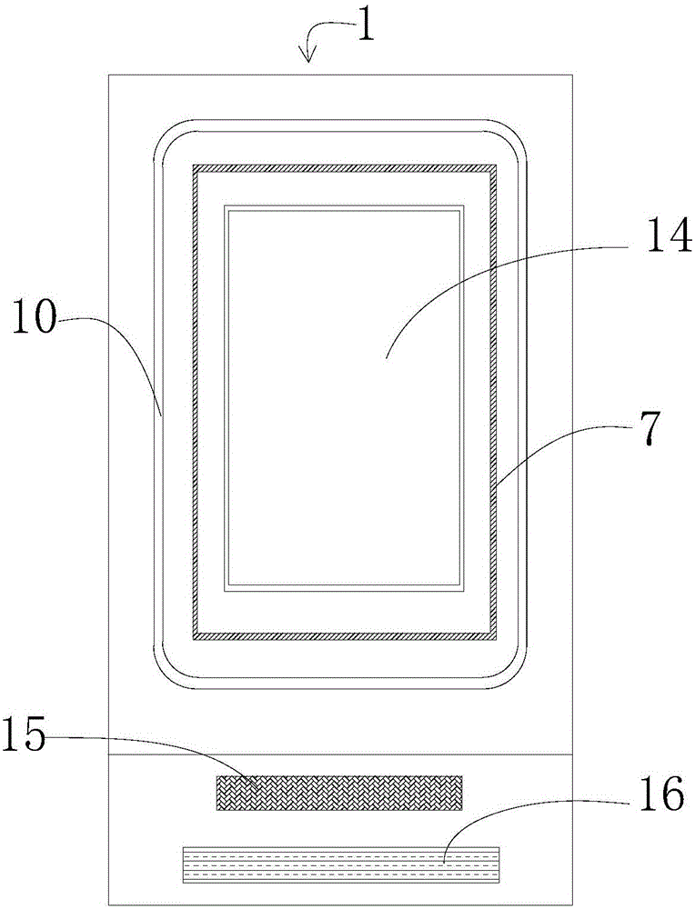
[0023] Such as figure 1 As shown, it is a schematic diagram of the overall structure of the second glass substrate 2 of the liquid crystal display panel 1 in the prior art, from figure 1 It can be seen that the display area 14 (ActiveArea area, also referred to as AA area) of the liquid crystal display panel 1 is set in the middle of the liquid crystal display panel...


PUM


Abstract

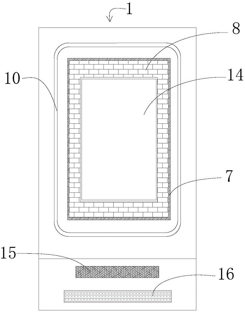
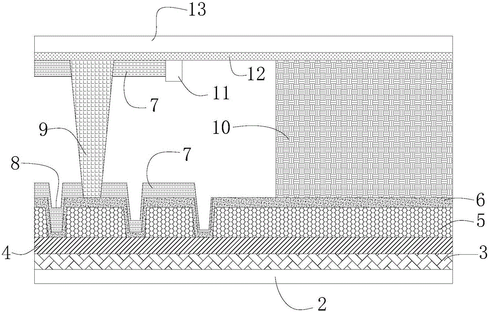
The invention provides a liquid crystal display panel. The liquid crystal display panel comprises a first glass substrate and a second glass substrate. Multiple spacing structures are arranged on the inner side of the first glass substrate, and frame glue is arranged on the periphery of the first glass substrate. A flat layer is formed on the inner side of the second glass substrate. A display region is arranged in the middle of the liquid crystal display panel. The frame glue is used for connecting the first glass substrate with the second glass substrate. The display region is arranged in the range defined by the frame glue. The area of the display region is smaller than that defined by the frame glue, and grid-shaped grooves are formed in the region between the outer edge of the display region and the inner edge of the frame glue. According to the liquid crystal display panel, the sealing performance between the first glass substrate and the second glass substrate can be guaranteed, the gap between the first glass substrate and the second glass substrate is not affected, and the phenomenon of non-uniform color or color differences of the periphery of the liquid crystal display panel is avoided.

Description

【Technical field】 [0001] The invention relates to the technical field of liquid crystal displays, in particular to a liquid crystal display panel. 【Background technique】 [0002] With the continuous popularization of liquid crystal display panels, people have higher and higher requirements on the functions of some components of the liquid crystal display panel. In recent years, due to the development trend of narrow bezels of LCD panels, it is necessary to design the distance between the effective display area of ​​the LCD panel, that is, the AA area and the frame rubber area, to be relatively close, which leads to a problem, that is, when the LCD panel When the distance between the display area and the frame glue area is relatively short, when the alignment liquid is applied to the display area to form an alignment film, because the alignment liquid has fluidity, its stop line is not easy to control, and it is easy to flow to the frame glue area and damage the frame glue T...

Claims


Application Information

Patent Timeline
IPC IPC(8): G02F1/1339
CPCG02F1/13394G02F1/1337G02F1/1339
Inventor 陈彩琴
Owner TCL CHINA STAR OPTOELECTRONICS TECH CO LTD
Learn More