Buffer synchronization mechanism between double storage controllers

A dual-controller, synchronization mechanism technology used in memory addressing/allocation/relocation, input/output to record carrier, etc.

Active Publication Date: 2015-11-11
SHANDONG CHAOYUE DATA CONTROL ELECTRONICS CO LTD
View PDF5 Cites 14 Cited by
  • Summary
  • Abstract
  • Description
  • Claims
  • Application Information

AI Technical Summary

Problems solved by technology

Solve the problem that the additional overhead of slave controller cache synchronization in traditional cache synchronization implementation affects the processing efficiency of the controller

Method used


Image

  • Buffer synchronization mechanism between double storage controllers

Examples


Embodiment 1

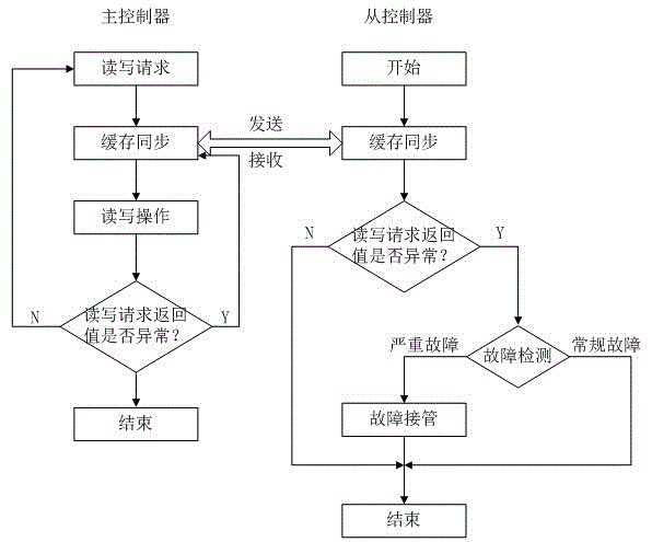
[0029] A cache synchronization mechanism between dual storage controllers of the present invention uses a 10G network connection between the dual storage controllers, and the mutual communication is completed by the heartbeat process and the cache synchronization process, specifically using the socket of the kernel layer;

[0030] The implementation of the cache synchronization function is divided into the implementation of the cache synchronization process and the heartbeat process; the cache synchronization process is divided into a master-slave work mode, and the initiation of the cache synchronization process is triggered by read and write requests and read and write exceptions in the master work mode. In the working mode, combined with the heartbeat process for fault detection and then transferred to the processing of the fault takeover thread; when the read and write returns to normal, it can respond to the client request without waiting for the completion of the cache fro...

Embodiment 2

[0035] A cache synchronization mechanism between dual storage controllers of the present invention uses a 10G network connection between the dual storage controllers, and the mutual communication is completed by the heartbeat process and the cache synchronization process, specifically using the socket of the kernel layer;

[0036] The implementation of the cache synchronization function is divided into the implementation of the cache synchronization process and the heartbeat process; the cache synchronization process is divided into a master-slave work mode, and the initiation of the cache synchronization process is triggered by read and write requests and read and write exceptions in the master work mode. In the working mode, combined with the heartbeat process for fault detection and then transferred to the processing of the fault takeover thread; when the read and write returns to normal, it can respond to the client request without waiting for the completion of the cache fro...


PUM


Abstract

The invention discloses a buffer synchronization mechanism between double storage controllers, and belongs to the technical field of double storage controllers. The buffer synchronization mechanism solves the problem of influence on the controller processing efficiency due to the additional increase of expenditure of standby controller buffer synchronization during the conventional buffer synchronization realization. The buffer synchronization mechanism between the double storage controllers has the technical scheme that the double storage controllers are connected through a 10 gigabit network; the mutual communication is completed through a heartbeat process and a buffer synchronization process; the operation is concretely completed by using a socket of a kernel layer; the realization of the buffer synchronization function comprises the buffer synchronization process realization and the heartbeat process realization; the buffer synchronization process is divided into an active-standby work mode; in the active work mode, the initiation of the buffer synchronization process is triggered through a reading-writing request and a reading-writing abnormity in the active work mode; in the standby work mode, the heartbeat process is combined for fault detection, and then, the operation is transferred to the fault take-over thread handling; and a buffer synchronous communication protocol data packet comprises the command type, the logic disc address, the physical equipment number, the data size and the data and reading-writing return value.

Description

technical field [0001] The present invention relates to the technical field of dual storage controllers, specifically a cache synchronization mechanism between dual storage controllers. Background technique [0002] The current storage system architecture has evolved from traditional direct storage (DAS) to network-attached storage (NAS) architecture and storage area network (SAN) architecture. SAN (StorageAeraNetwork-Storage Area Network) is a storage architecture that connects storage devices and application servers through a network. This network is dedicated to access between hosts and storage devices. When there is a demand for data access, the data can be transmitted at high speed between the server and the background storage device through the storage area network. The realization of the SAN architecture depends on the storage-side SCSITarget software, which makes it possible for the SCSI protocol to be applied to high-speed data transmission networks. The SAN archi...

Claims


Application Information

Patent Timeline
Patent Type & Authority Applications(China)
IPC IPC(8): G06F3/06G06F12/08
Inventor 李丽吴登勇刘维霞
Owner SHANDONG CHAOYUE DATA CONTROL ELECTRONICS CO LTD
Why Eureka
Try Eureka