Pay-off device of tubular strander

A pay-off device and tube stranding machine technology, which is applied in the manufacture of electrical components, circuits, cables/conductors, etc., can solve the problems of broken wires, poor production efficiency of tube stranding machines, and a large number of man-hours, so as to reduce broken wires, Comprehensive man-hour consumption reduction, the effect of smooth outlet

Inactive Publication Date: 2015-11-11
TIANJIN JINGWEI HUIKAI OPTOELECTRONICS CO LTD
View PDF0 Cites 2 Cited by
  • Summary
  • Abstract
  • Description
  • Claims
  • Application Information

AI Technical Summary

Problems solved by technology

[0005] However, in the case of using such a pay-off reel, when the wire is paid out to both sides of the pay-off reel, if the wire is pressed by the lower layer wire, the angle of intersection between the lower layer wire and the wire to be released is large, The pressing point is one point, and the pressing force is concentrated on one point, so it is easy to cause the wire of the wire to break. At this time, the wire must be stopped and welded to continue production. The welding work consumes a lot of man-hours and makes the overall production of the pipe stranding machine difficult. Efficiency becomes worse

Method used


Image

  • Pay-off device of tubular strander
  • Pay-off device of tubular strander

Examples


Embodiment Construction

[0017] Next, a pay-off device for a tubular strander as an example of the present invention will be described based on the drawings.

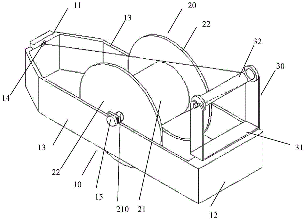
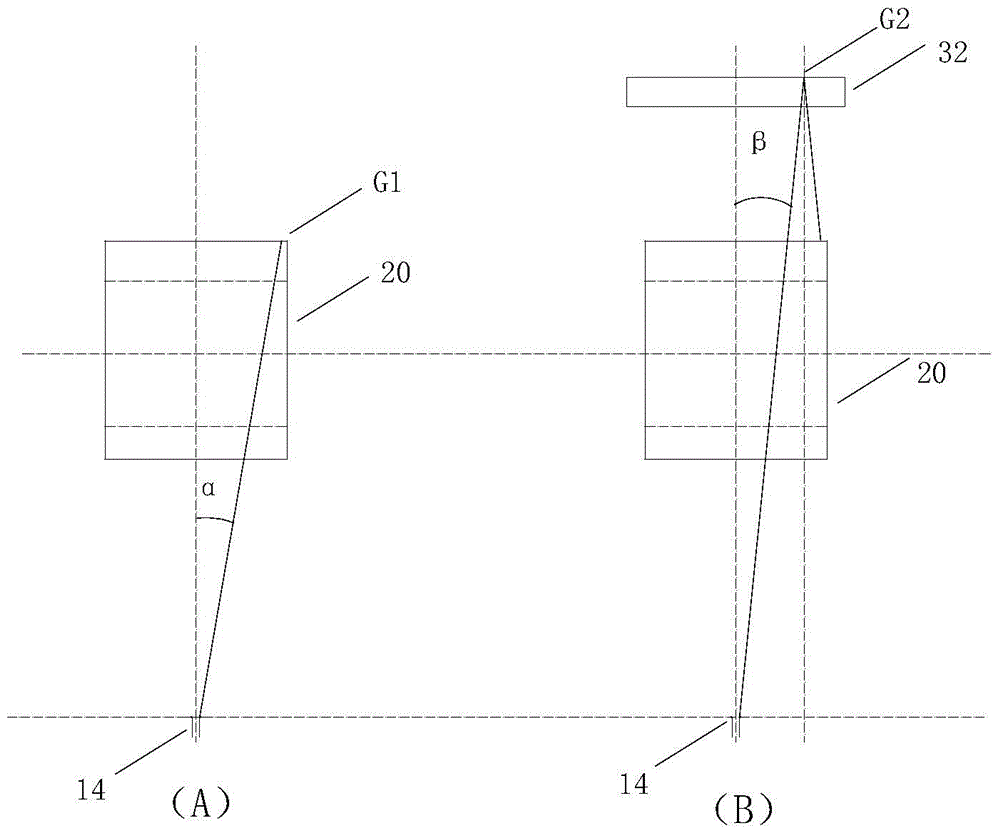
[0018] figure 1 It is a schematic perspective view showing the pay-off device of the pipe stranding machine of the present invention. figure 2 It is a schematic diagram showing the principle of the pay-off device of the pipe strander of the present invention.

[0019] Such as figure 1 As shown, the pay-off device of the pipe strander of the present invention has a pay-off cradle support 10 , a pay-off reel 20 and an auxiliary guiding device 30 .

[0020] The wire-paying cradle support 10 is formed into a frame shape, has a front wall 11, a rear wall 12 and two side walls 13 that are positioned at both sides of the front wall 11 and the rear wall 12 to connect the front wall 11 and the rear wall 12 together. A threading hole 14 is formed on the wall 11 .

[0021] The payout reel 20 has a winding shaft 21 wound with wires and baffles 22 loca...


PUM


Abstract

Provided in the invention is a pay-off device of a tubular strander. With the pay-off device, a wire breaking phenomenon can be avoided. The pay-off device comprises a pay-off cradle support, a pay-off plate, and an auxiliary guiding device. To be specific, the pay-off cradle support in a frame shape has a front wall, a rear wall, two side walls that are arranged at the two sides of the front wall and the rear wall and connect the front wall and the rear wall together; and a wire through hole is formed in the front wall. The pay-off plate includes a winding shaft wound with a lead and baffle plates arranged at the two sides of the winding shaft; and the pay-off plate is erected on the two side walls of the pay-off cradle support in a rotating mode. The auxiliary guiding device includes a guide roller support arranged at the rear wall of the pay-off cradle support vertically and a guide roller; the two ends of the guide roller are supported by the guide roller support and the guide roller can rotate freely; and the axial direction of the guide roller is identical with that of the winding shaft of the pay-off plate. A lead extends into the wire through hole by the guide roller from the pay-off plate.

Description

technical field [0001] The invention relates to a pay-off device of a pipe stranding machine. Background technique [0002] At present, in the power transmission and transformation projects of the State Grid, cables and the like are usually composed of twisted wires, which are formed by transposing a single wire. When making such twisted wires, a tubular stranding machine is usually used. The tube stranding machine can transpose copper wire, aluminum wire or steel wire to form stranded wire. [0003] A pay-off device is provided at the input end of such a pipe strander, which transports the wires wound on the pay-off reel to the pipe strander. The pay-off device is composed of a pay-off cradle bracket and a pay-off reel. Threading holes are formed on the front wall of the cradle, and the pay-off reel can be rotatably erected on the two side walls of the pay-off cradle support. [0004] When using such a pay-off device, the wire wound on the pay-off reel is wound from the r...

Claims


Application Information

Patent Timeline
Patent Type & Authority Applications(China)
IPC IPC(8): H01B13/02
Inventor 董树林聂书红王保飞聂广浩
Owner TIANJIN JINGWEI HUIKAI OPTOELECTRONICS CO LTD
Why Eureka
Try Eureka