Cellular cavity-stage integrated fuel cell electrode and preparation method thereof

A fuel cell electrode, honeycomb technology, applied in the direction of battery electrodes, circuits, electrical components, etc., can solve the problems of increased fuel transmission resistance, reduced battery performance, complicated assembly and sealing, etc., to improve discharge current, simple and compact structure, Easy to assemble and seal

Inactive Publication Date: 2015-11-11
江苏汉瓦特电力科技有限公司
View PDF4 Cites 7 Cited by
  • Summary
  • Abstract
  • Description
  • Claims
  • Application Information

AI Technical Summary

Problems solved by technology

[0002] The structure of the traditional fuel cell is that the fuel chamber, the collector plate, the diffusion layer and the catalytic layer are closely arranged in sequence. This separation arrangement of the fuel chamber, the collector plate, the diffusion layer and the catalytic layer makes the size of the battery larger , the assembly and sealing are complicated, and the transmission resistance of fuel increases, thereby reducing the performance of the battery

Method used


Image

  • Cellular cavity-stage integrated fuel cell electrode and preparation method thereof
  • Cellular cavity-stage integrated fuel cell electrode and preparation method thereof
  • Cellular cavity-stage integrated fuel cell electrode and preparation method thereof

Examples


Embodiment Construction

[0025] The present invention is described in further detail below in conjunction with accompanying drawing:

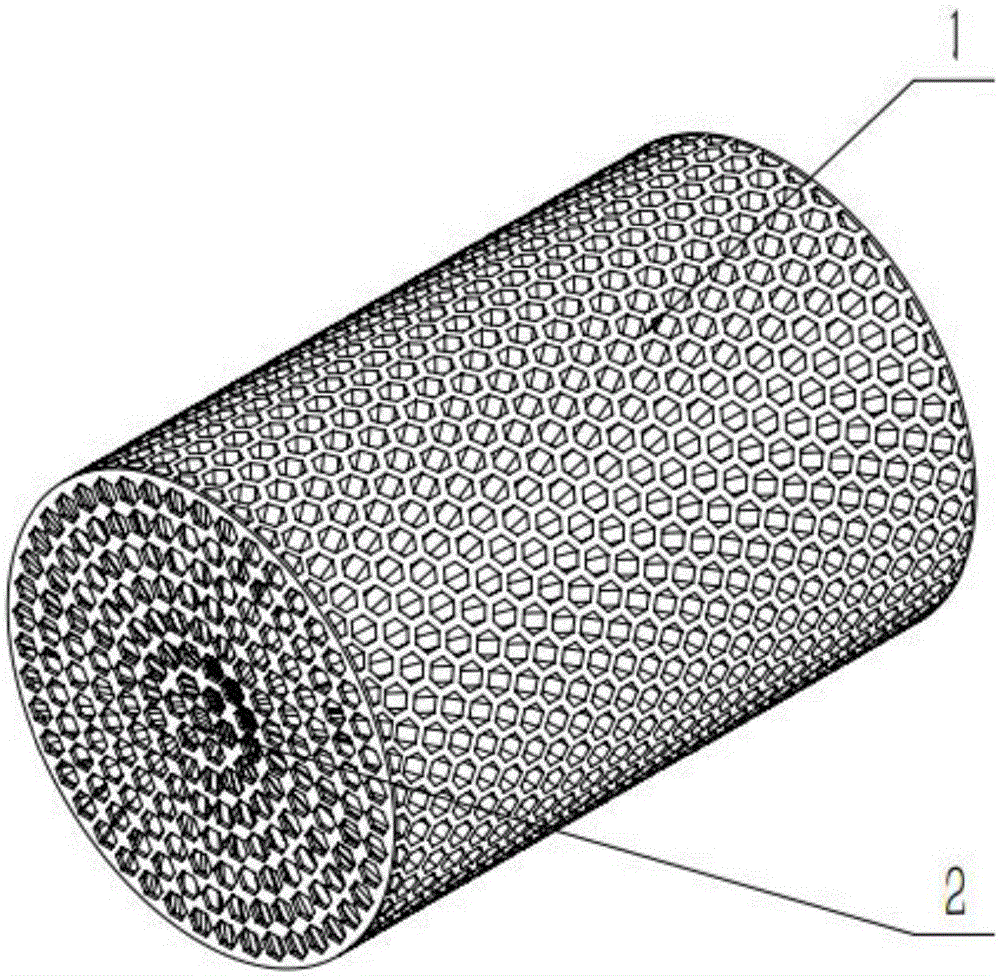
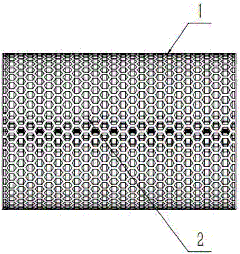
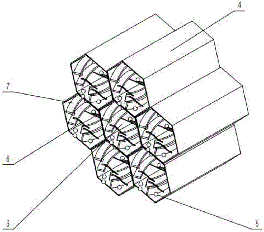
[0026] see Figures 1 to 4 , the fuel cell electrode with honeycomb cavity and electrode integration of the present invention includes a cylindrical fuel cavity 1 made by 3D printing using conductive 3D printing materials, and a number of honeycomb holes 2 are opened on the side and bottom of the fuel cavity 1, The outside of the honeycomb hole 2 is a honeycomb porous structure support layer 4; the side honeycomb hole 2 is used as the primary channel 3 of the fuel transmission channel, and the honeycomb hole 2 is provided with a secondary channel 7 for increasing the reaction surface area; The surfaces of the primary channel 3 and the secondary channel 7 are coated with a thin-film catalytic layer, and the thin-film catalytic layer includes catalyst particles 5 and ionic polymers 6 coated on the surfaces of the primary channel 3 and the secondary channel 7 .

[0027] ...


PUM


Abstract

The invention discloses a cellular cavity-stage integrated fuel cell electrode and a preparation method of the fuel cell electrode and belongs to the field of a fuel cell. Integrated design and manufacture of a cellular porous structure diffusion layer and a catalyst layer is contained. The cellular porous structure is formed by using a conductive 3D printing material to fast print. A cavity, a collector plate, the diffusion layer and the catalyst layer of the cellular porous structure in the cellular cavity-stage integrated fuel cell electrode are integrated to break through a design manner of separating the cavity, the collector plate, the diffusion layer and the catalyst layer in a traditional fuel cell. In the cellular porous structure, second-stage channels are distributed on the basis of first-stage channels, and therefore, such design greatly increases the catalytic activity superficial area, reduces mass transfer resistance and greatly improves discharging current of the electrode, and enables the structure of the electrode to be simple and compact, and the assembly and sealing to be convenient and easy.

Description

【Technical field】 [0001] The invention belongs to the field of fuel cells, and in particular relates to a honeycomb cavity-electrode integrated fuel cell electrode and a preparation method thereof. 【Background technique】 [0002] The structure of the traditional fuel cell is that the fuel chamber, the collector plate, the diffusion layer and the catalytic layer are closely arranged in sequence. This separation arrangement of the fuel chamber, the collector plate, the diffusion layer and the catalytic layer makes the size of the battery larger , The assembly and sealing are complicated, and the transmission resistance of the fuel increases, thereby reducing the performance of the battery. 【Content of invention】 [0003] The object of the present invention is to solve the above problems, and provide a fuel cell electrode with a honeycomb cavity-electrode integration and a preparation method thereof. Connected to form a first-level channel, and each hole is also distributed ...

Claims


Application Information

Patent Timeline
Patent Type & Authority Applications(China)
IPC IPC(8): H01M4/86H01M4/88
CPCH01M4/8605H01M4/8875Y02E60/50
Inventor 李印实陈杰贾哲姜飒
Owner 江苏汉瓦特电力科技有限公司
Why Eureka
Try Eureka