Magnetic bearing ring of micro Hall motor

A technology of a micro-Hall motor and a magnetic bearing ring, applied in the field of magnetic bearing rings, can solve the problems of uneven magnetic distribution of nylon magnetic rings, high cost of installing bushings, complicated process and high cost, and avoid uneven magnetic distribution, The effect of avoiding magnetic pole pointing deviation and simplifying the fixing process

Active Publication Date: 2015-11-11
芜湖双林汽车部件有限公司
View PDF3 Cites 0 Cited by
  • Summary
  • Abstract
  • Description
  • Claims
  • Application Information

AI Technical Summary

Problems solved by technology

[0003] The existing technology uses ring-shaped nylon permanent magnets or NdFeB magnets as the measuring rotation magnets, which are referred to as nylon magnetic rings and NdFeB magnetic rings respectively. Nylon magnetic rings or NdFeB magnetic rings are fixed to the on the rotor shaft of the motor, see Figure 7 ;Because the nylon magnetic ring will be stretched and deformed after being press-fitted, the deformation will change the direction of the magnetic chips that have been magnetized and arranged neatly, resulting in uneven magnetic distribution of the nylon magnetic ring, resulting in signal disorder when the motor is running; Because the NdFeB magnetic ring is brittle, it will be brittle and damaged when it is press-fitted on the rotor shaft, and the NdFeB magnetic ring will crack or break when the motor is running at high speed. A copper or aluminum bushing for transition is installed between the boron magnetic ring and the motor shaft; however, the process of installing the bushing is complicated and costly, so the existing technology has problems of uneven magnetic distribution, or complicated process and high cost Problems and deficiencies

Method used


Image

  • Magnetic bearing ring of micro Hall motor
  • Magnetic bearing ring of micro Hall motor
  • Magnetic bearing ring of micro Hall motor

Examples


Embodiment Construction

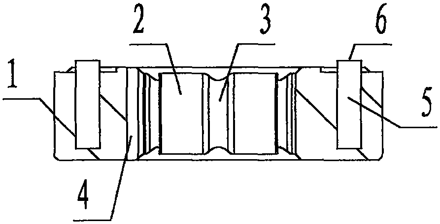
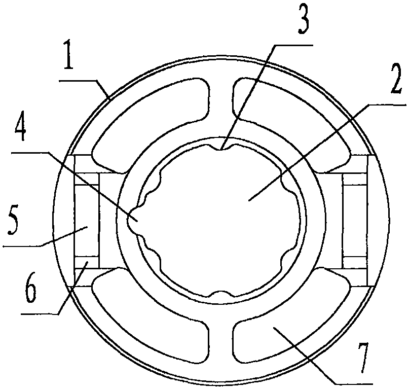
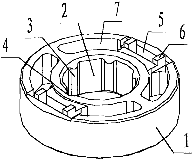
[0027] refer to Figure 1 to Figure 6 , a magnetic bearing ring of a micro-Hall motor of the present invention is composed of a ring body 1, a shaft hole 2, an interference rib 3, an orientation groove 4, a magnetic core groove 5, a heat fusion platform 6 and a mesopore 7, and the The ring body 1 is a circular cylindrical plastic member; the center of the ring body 1 is provided with a circular through hole in the up and down direction called the shaft hole 2, and the hole wall of the shaft hole 2 is evenly equipped with a number of centripetal protrusions. The protruding ribs in the exit and up and down directions are called interference ribs 3, and the left side of the hole wall of the shaft hole 2 is provided with a vertical groove with a semicircular cross section called the orientation groove 4; the left and right grooves on the ring body 1 Both sides, centering on the shaft hole 2, are symmetrically provided with rectangular grooves called magnetic core grooves 5, and th...


PUM


Abstract

The invention discloses a magnetic bearing ring of a micro Hall motor. The magnetic bearing ring comprises a ring body (1), a bearing hole (2), interference ribs (3), a positioning groove (4), magnetic core grooves (5), hot melting tables and mesoporous (7). According to the technical scheme, magnetic cores which are not magnetized are firstly embedded into the magnetic core grooves and fixed by hot-melting flattening of the hot melting tables, and then the magnetic cores are directionally magnetized based on the positioning groove, and finally the ring body is arranged on a rotor shaft of the motor through the shaft hole in an interference press manner, therefore, the problems and the defects of non-uniform magnetic distribution or high process complexity and low cost are solved; and through the arrangement of a rotation detection magnet of the micro Hall motor, the purposes of uniform magnetic distribution, process simplicity and cost reduction are achieved.

Description

technical field [0001] The invention relates to a micro-Hall motor, in particular to a magnetic bearing ring of a micro-Hall motor used to carry a rotation measuring magnet. Background technique [0002] The rotor shaft of the micro-Hall motor is equipped with a permanent magnet used to cooperate with the Hall element to measure the number of rotor rotations; hereinafter, the micro-Hall motor is referred to as the motor, and the permanent magnet used for measuring rotation is referred to as the measuring rotation magnet; [0003] The existing technology uses ring-shaped nylon permanent magnets or NdFeB magnets as the measuring rotation magnets, which are referred to as nylon magnetic rings and NdFeB magnetic rings respectively. Nylon magnetic rings or NdFeB magnetic rings are fixed to the on the rotor shaft of the motor, see Figure 7 ;Because the nylon magnetic ring will be stretched and deformed after being press-fitted, the deformation will change the direction of the mag...

Claims


Application Information

Patent Timeline
Patent Type & Authority Applications(China)
IPC IPC(8): H02K1/28
Inventor 雷鹏飞谢元辉王延斌
Owner 芜湖双林汽车部件有限公司
Why Eureka
Try Eureka