Voltage-sharing DC capacitor system for large-power frequency converter

A technology of DC capacitors and frequency converters, applied in the field of frequency converters, can solve problems such as increasing complexity

Inactive Publication Date: 2015-11-11
上海三环节能科技发展股份有限公司
View PDF7 Cites 2 Cited by
  • Summary
  • Abstract
  • Description
  • Claims
  • Application Information

AI Technical Summary

Problems solved by technology

The heat dissipation and insulation problems must be considered in the design of the unit structure, which increases the complexity

Method used


Image

  • Voltage-sharing DC capacitor system for large-power frequency converter
  • Voltage-sharing DC capacitor system for large-power frequency converter

Examples


Embodiment 1

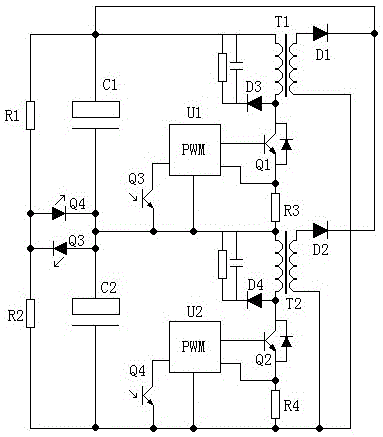
[0017] Such as figure 1 As shown, a voltage equalizing DC capacitor system for a high-power frequency converter, the high-power frequency converter voltage equalizing DC capacitor system includes a first capacitor C1, a second capacitor C2, a first boost converter, a second boost converter , a first sampling resistor R1, a second sampling resistor R2, and a signal controller, the first capacitor C1 is connected in parallel with the first boost converter, the second capacitor C2 is connected in parallel with the second boost converter, and the first A capacitor C1 is connected in parallel with the first sampling resistor R1, the second capacitor C2 is connected in parallel with the second sampling resistor R2, the first capacitor C1 is connected in series with the second capacitor C2, and the first sampling resistor R1 is connected with the second sampling resistor R2 is connected in series, the first sampling resistor R1 and the second sampling resistor R2 are respectively con...

Embodiment 2

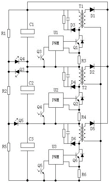
[0025] Such as figure 2 As shown, when it is necessary to equalize the voltage of three groups of capacitors in series, the figure 1 On the basis, a third boost converter is added to make C1 and C2 basically equalize the voltage, and C3 and C2 also basically equalize the voltage, which realizes the purpose of basically equalizing the voltage of the three sets of capacitors, and the mutual voltage difference does not exceed 1V.

[0026] The third boost converter includes a pulse width modulator U3, a main switch tube Q6, a current detection resistor R6, a step-up transformer T3, a rectifier diode D5, and a rectifier diode D6. The width modulator U3 is connected, the main switch tube Q6 is connected to the current detection resistor R6, the main switch tube Q6 is connected to the step-up transformer T3, and the rectifier diode D5 and the rectifier diode D6 are respectively connected to the step-up transformer T3 , the rectifier diode D5 is connected to the main switch tube Q6, a...


PUM


Abstract

The invention discloses a voltage-sharing DC capacitor system for a large-power frequency converter, and the system comprises a first capacitor C1, a second capacitor C2, a first boost converter, a second boost converter, a first sampling resistor R1, a second sampling resistor, and a signal controller, wherein the first capacitor is in parallel connection with the first boost converter. The second capacitor C2 is in parallel connection with the second boost converter, and the first capacitor C1 is in parallel connection with the first sampling resistor R1. The second capacitor C2 is in parallel connection with the second resistor C2. The first capacitor C1 is in series connection with the second capacitor C2, and the firs sampling resistor R1 is in series connection with the second sampling resistor R2. The first sampling resistor R1 and the second sampling resistor R2 are respectively connected with the signal controller. The first and second boost converters are respectively connected with the signal controller. The first and second boost converters are connected with each other. The system in the above structure is simple in structure and is reliable and stable in voltage sharing of capacitors.

Description

technical field [0001] The invention relates to the technical field of frequency converters, in particular to a voltage equalizing DC capacitor system for high-power frequency converters. Background technique [0002] A large number of DC capacitors are used in inverters, especially high-voltage inverters. At present, mainstream inverters are still implemented in series and parallel with electrolytic capacitors, because there are deviations in the parameters of electrolytic capacitors, which may cause the problem of capacitor voltage equalization, that is, partial capacitance The voltage is too high, and the voltage of some capacitors is too low. In extreme cases, it may cause the failure of the high voltage capacitor. Ordinary inverters have at least 2 sets of capacitors in series, while high-voltage inverters need 3-4 sets of capacitors in series, so the problem of voltage equalization is more prominent. [0003] Generally, voltage equalizing resistors are used in frequen...

Claims


Application Information

Patent Timeline
Patent Type & Authority Applications(China)
IPC IPC(8): H02M1/34
Inventor 李其荣李小桂周继红计君
Owner 上海三环节能科技发展股份有限公司
Why Eureka
Try Eureka