
A slip motor automatic speed regulation control device

An automatic speed regulation and control device technology, applied in the direction of AC motor control, control system, electrical components, etc., can solve the problems of poor stability of semiconductor devices, etc., and achieve the effects of stable circuit performance, convenient and high-precision control, and strong oscillation frequency

Inactive Publication Date: 2017-10-27
郑州天河通信科技有限公司 +2
View PDF4 Cites 0 Cited by
  • Summary
  • Abstract
  • Description
  • Claims
  • Application Information

AI Technical Summary

Problems solved by technology

[0003] The purpose of the present invention is to provide a slip motor automatic speed regulation control device to solve the problem of poor stability of semiconductor devices in the phase-shift trigger circuit

Method used


Image

  • A slip motor automatic speed regulation control device
  • A slip motor automatic speed regulation control device
  • A slip motor automatic speed regulation control device

Examples


Embodiment Construction

[0028] The present invention will be described in further detail below in conjunction with the accompanying drawings.

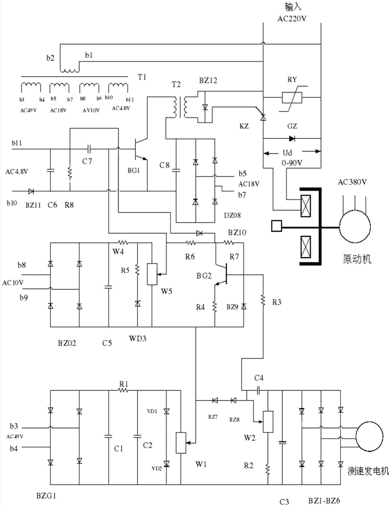
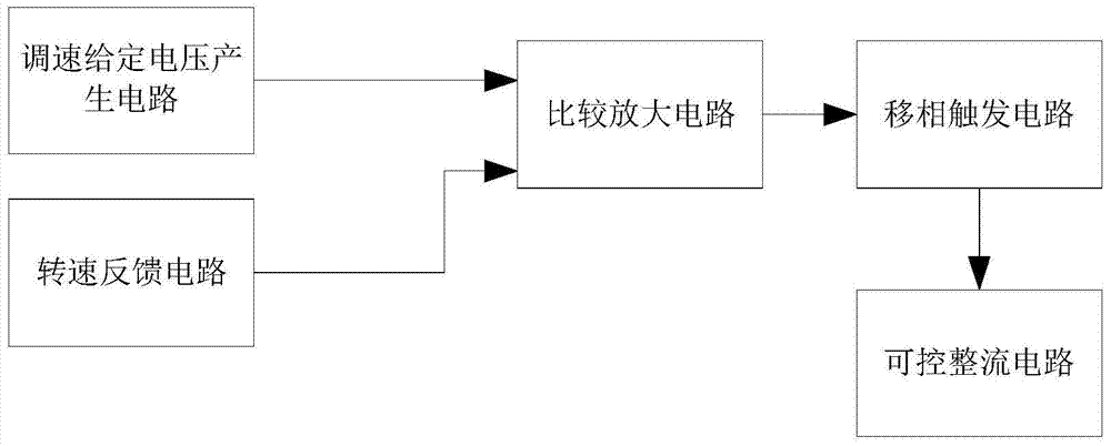
[0029] Such as figure 2 The automatic speed regulation control device shown includes: a phase-shift trigger circuit, a comparison amplifier circuit, a speed regulation given voltage generation circuit, a speed feedback circuit and a controllable rectification circuit, and the output end of the speed regulation given voltage generation circuit and the speed feedback circuit Connect the input terminal of the comparison amplifier circuit, the output terminal of the comparison amplifier circuit is connected to the input terminal of the phase-shift trigger circuit, the output terminal of the phase-shift trigger circuit is connected to the thyristor in the controllable rectification circuit, and the controllable rectification circuit is connected in series with the excitation coil on the power supply circuit.

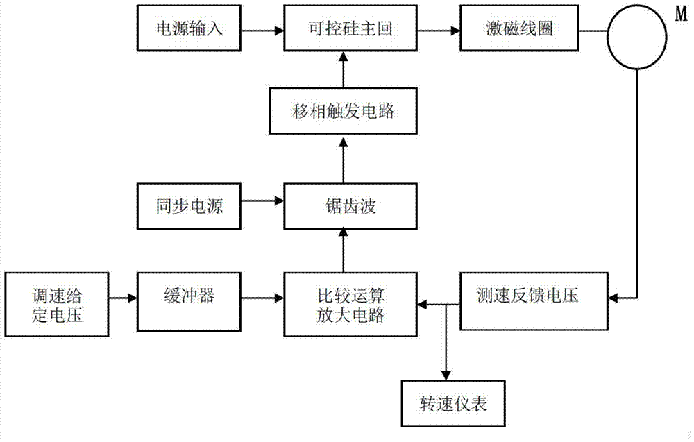
[0030] Such as image 3 As shown, the voltage signa...


PUM


Abstract

The invention relates to an automatic speed regulation control device for a slip motor, comprising: a phase shift trigger circuit, a comparison amplifier circuit, a speed regulation given voltage generation circuit, a speed feedback circuit and a controllable rectification circuit, a speed regulation given voltage generation circuit and The output terminal of the speed feedback circuit is connected to the input terminal of the comparison amplifier circuit, the output terminal of the comparison amplifier circuit is connected to the input terminal of the phase-shift trigger circuit, and the output terminal of the phase-shift trigger circuit is connected to the thyristor in the controllable rectification circuit, and the controllable rectification circuit It is connected in series with the power supply circuit of the excitation coil. The operational amplifier has high stability in use, and the use of the operational amplifier can make the circuit performance stable, safe and reliable. Also, operational amplifiers are relatively inexpensive. In addition, the use of 555 multivibrator in the phase-shift trigger circuit can obtain high-precision oscillation frequency and strong power output capability, and can effectively control the conduction of the thyristor, which is convenient for high-precision control of motor speed regulation.

Description

technical field [0001] The invention relates to an automatic speed regulation control device for a slip motor, which belongs to the field of motor automatic speed regulation control. Background technique [0002] Such as figure 1 Shown is the existing slip motor speed control circuit diagram, including the following components: motor main circuit, given voltage circuit, comparison amplifier circuit and phase-shift trigger circuit, etc., most of which are composed of discrete components , where semiconductor devices are mainly used: such as transistor triodes, and the trigger device is a unijunction transistor. Semiconductor devices have some inherent characteristics. Due to these inherent characteristics, semiconductor devices are easily affected by the surrounding working environment. Changes in surrounding environmental conditions will cause instability in the operating point of semiconductor devices, and when selecting semiconductor devices, if If the relevant parameter...

Claims


Application Information

Patent Timeline
Patent Type & Authority Patents(China)
IPC IPC(8): H02P23/00H02P25/02
Inventor 宋广平
Owner 郑州天河通信科技有限公司
Learn More