Modular exhaust treatment system

A technology for exhaust treatment and exhaust post-treatment, which is applied in the direction of exhaust devices, gas passages, machines/engines, etc., and can solve problems such as the infeasibility of exhaust after-treatment pipelines

Inactive Publication Date: 2015-11-11
TENNECO AUTOMOTIVE OPERATING CO INC
View PDF5 Cites 0 Cited by
  • Summary
  • Abstract
  • Description
  • Claims
  • Application Information

AI Technical Summary

Problems solved by technology

However, a linear exhaust aftertreatment pipeline may not be feasible due to the many different package constraints that may exist for the corresponding application

Method used


Image

  • Modular exhaust treatment system
  • Modular exhaust treatment system
  • Modular exhaust treatment system

Examples


Embodiment Construction

[0019] Example embodiments will now be described in more detail with reference to the accompanying drawings.

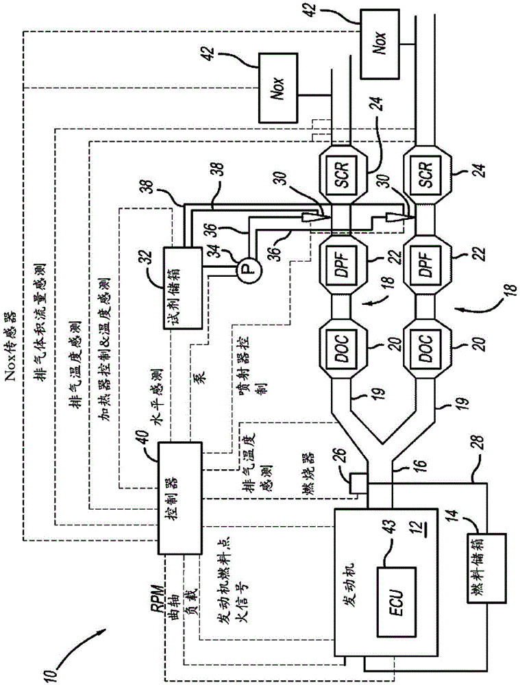
[0020] figure 1 is a schematic illustration of an exhaust system 10 according to the present disclosure. Exhaust system 10 includes at least one engine 12 in communication with a fuel source 14 that, upon consumption, produces exhaust gases that are discharged into exhaust passage 16 that includes an exhaust aftertreatment system 18 . The exhaust system 10 may be designed as a multi-branch system with a plurality of exhaust lines 19 each comprising an aftertreatment system 18 . although figure 1 Only one pair of exhaust lines 19 are shown, it being understood that a greater number of exhaust lines 19 may be used depending on the size of the engine 12 and the resulting exhaust flow rate without departing from the scope of the present disclosure.

[0021] Each exhaust aftertreatment system 18 may include a diesel oxidation catalyst (DOC) component 20 , a diesel parti...


PUM


Abstract

A modular exhaust after-treatment system including a plurality of exhaust after-treatment modules. Each module includes a housing defining a non-linear flow path arranged between an inlet passage and an outlet passage. The non-linear flow path includes a first portion adjacent the inlet passage that includes a first exhaust treatment component, a second portion downstream from the first portion, and a third portion downstream from second portion adjacent the outlet passage, wherein the third portion includes a second exhaust treatment component. The plurality of exhaust after-treatment modules are secured to each other in either horizontally or vertically.

Description

technical field [0001] The present disclosure relates to modular exhaust aftertreatment systems. Background technique [0002] This section provides background information related to the present disclosure which is not necessarily prior art. [0003] Large diesel engines used in locomotives, marine applications, and stationary applications may have exhaust flow rates that exceed the capabilities of a single exhaust line. The exhaust system used for each of the applications indicated above may thus be designed as a multi-branch system with a plurality of exhaust lines each comprising an exhaust aftertreatment system. However, a linear exhaust aftertreatment pipeline may not be feasible due to various package constraints that may exist for the corresponding application. Thus, it has recently become necessary to develop an exhaust aftertreatment system that can efficiently treat exhaust in a non-linear configuration. Contents of the invention [0004] This section provides...

Claims


Application Information

Patent Timeline
IPC IPC(8): F01N3/28F01N3/10F01N13/08
CPCF01N3/08F01N3/021F01N3/2066F01N13/009F01N13/017F01N2470/18F01N2590/02F01N2590/08F01N2590/10Y02T10/24F01N3/106Y02T10/12
Inventor 迈克尔·戈林郑贯宇蒂莫西·P·加德纳保罗·马耶夫斯基
Owner TENNECO AUTOMOTIVE OPERATING CO INC
Why Eureka
Try Eureka