cooking utensils
A technology for cooking utensils and outer pots, which is applied in the field of kitchen utensils and cooking utensils. It can solve the problems of complex structure of the pot body, affecting the convenience of using electric pressure, increasing volume and weight, etc., so as to reduce the phenomenon of overflow, simple structure, Ease of use and portability
- Summary
- Abstract
- Description
- Claims
- Application Information
AI Technical Summary
Problems solved by technology
Method used
Image
Examples
Embodiment 1
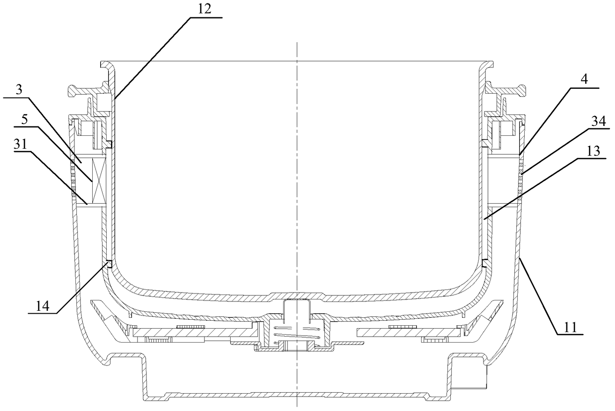
[0051] figure 1 It is a schematic structural diagram of a cooking appliance provided by an embodiment of the present invention. Such as figure 1 As shown, this embodiment provides a cooking appliance, including: a pot body, a pot cover, a fan, and a heating device; the pot body includes an outer pot body 11 and an inner pot 12 arranged in the outer pot body 11, and A heating device is arranged under the inner tank 12; an air duct 13 is formed between the inner surface of the outer tank 11 and the outer surface of the inner tank 12, and a partition wall 14 is provided between the inner surface of the outer tank 11 and the outer surface of the inner tank 12. Surrounded by the inner surface of the outer pot body 11, the partition wall 14 and the outer surface of the inner liner 12; the fan 5 promotes the flow of external air in the air duct 13.
[0052] Specifically, the top of the outer pot body 11 is open, and the top of the outer pot body 11 can be provided with a lid that can be...
Embodiment 2
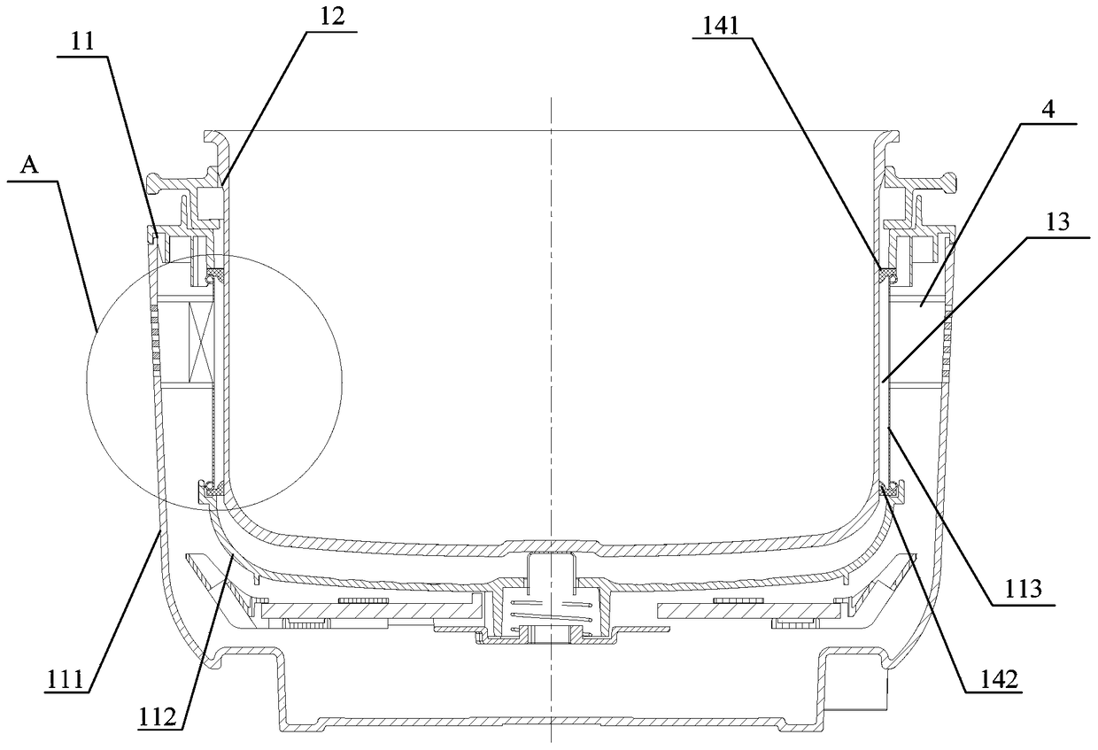
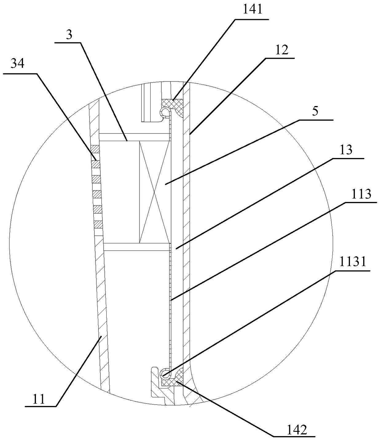
[0061] figure 2 Is a schematic structural diagram of a cooking appliance provided by another embodiment of the present invention, image 3 for figure 2 Enlarged view at center A. In this embodiment, on the basis of the first embodiment, a partition wall is provided on the outer pot body to form an air duct to further optimize the structure. Such as figure 2 As shown, the cooking appliance provided in this embodiment includes a pot body, a pot cover, a fan, and a heating device; the pot body includes an outer pot body 11 and an inner pot 12 arranged in the outer pot body. The heating device can be arranged in the outer pot body 11 corresponding to the inner pot. At the bottom of the tank 12 to heat the inner tank; the inner surface of the outer tank 11 is formed with a protruding partition wall, and the inner surface of the outer tank 11, the partition wall and the inner tank 12 enclose an air duct 13; wherein the partition wall 14 It can be integrally formed on the inner sur...
Embodiment 3
[0070] Figure 4 This is a partial schematic diagram of a cooking appliance provided by another embodiment of the present invention; the difference between this embodiment and the second embodiment is that the partition wall in this embodiment is arranged on the inner pot. Specifically, please refer to Figure 4 The cooking appliance of this embodiment may include a pot body, a pot cover and a fan; the pot body includes an outer pot body 11 and an inner pot 12 arranged in the outer pot body. The outer surface of the inner pot 12 is detachably installed with a partition wall 14 facing the inner pot. The partition wall 14 protruding from the outer surface 12, the inner surface of the outer pot 11 and the inner liner 12 jointly enclose an air duct 13. Among them, a variety of detachable installation methods can be used between the partition wall 14 and the inner liner 12, for example, a locking groove may be provided on the outer surface of the inner liner 12, and the inner edge ...
PUM
 Abstract
Description
Claims
Application Information
 - R&D
- Intellectual Property
- Life Sciences
- Materials
- Tech Scout
- Unparalleled Data Quality
- Higher Quality Content
- 60% Fewer Hallucinations
Browse by: Latest US Patents, China's latest patents, Technical Efficacy Thesaurus, Application Domain, Technology Topic, Popular Technical Reports.
© 2025 PatSnap. All rights reserved.Legal|Privacy policy|Modern Slavery Act Transparency Statement|Sitemap|About US| Contact US: help@patsnap.com


