Spoke air hole machining mold

A technology for processing molds and spokes, which is applied in the field of mechanical processing, can solve the problems of large punch force, deformation of spokes, wear of spokes, etc., and achieve the effects of small moving distance, avoiding wear and tear, and ensuring quality

Inactive Publication Date: 2015-11-18
CHONGQING DINGHAN MACHINERY
View PDF1 Cites 2 Cited by
  • Summary
  • Abstract
  • Description
  • Claims
  • Application Information

AI Technical Summary

Problems solved by technology

However, there is the following problem: in this patent, in order to punch holes, the spokes are fixed on the inclined wheel disc, and then punched by the punch of the upper die, but the downward force of the punch is relatively large, which is easy to The spoke part fixed on the wheel disc generates a huge impact force. At the same time, the wheel disc itself is relatively strong. Under the impact force of the punch, the spokes and the wheel disc are easy to cause the wear of the spokes, and it is easy to deform or lose the roundness of the spokes. Installed on the wheel There will be vibration up and down

Method used


Image

  • Spoke air hole machining mold

Examples


Embodiment Construction

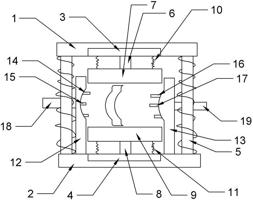
[0017] Such as figure 1 As shown, a spoke air hole processing mold includes an upper mold base 1, a lower mold base 2, an upper mold 3, a lower mold 4 and a guide column 5 for stamping, and the upper mold base 1 is located above the lower mold base 2, The upper mold 3 is fixedly connected with the depression on the lower end surface of the upper mold base 1, the lower mold 4 is fixedly connected with the depression on the upper end surface of the lower mold base 2, the guide columns 5 are located on both sides of the lower mold base 2, and the upper mold 3 is provided with a The guide hole that guide post 5 cooperates, and the guide post 5 on both sides is covered with stage clip above, is used for the guide of punching. The lower end of the upper die 3 is provided with an upper punch 6, and the upper punch 6 passes through the first elastic plate 7 positioned below the upper die 3, and the upper end of the lower die 4 is provided with a lower punch 8, and the lower punch 8 pa...


PUM


Abstract

The invention relates to the field of machining, in particular to a spoke air hole machining mold. The spoke air hole machining mold comprises an upper mold base, an upper mold body, a lower mold base and a lower mold body. The upper mold body and the upper mold base are connected in a matched manner. The lower mold body and the lower mold base are connected in a matched manner. An upper punch is arranged on the lower end face of the upper mold body. A lower punch is arranged on the upper end face of the lower mold body. A left elastic clamping plate and a right elastic clamping plate which are in sliding connection with the lower mold base are arranged on the lower mold base. Holes for the punches to penetrate are formed in the upper faces and the lower faces of the left elastic clamping plate and the right elastic clamping plate. The left elastic clamping plate is provided with a groove consistent with a spoke arc. A left protruding pin matched with a center hole of a spoke and left positioning pins matched with a spoke bolt hole are arranged on the upper face of the groove. The right elastic clamping plate is provided with a protruding groove matched with the left elastic clamping plate, and the groove is provided with right protruding pins and a right positioning pin. The spoke is vertically placed, the spoke is clamped and positioned through the left elastic clamping plate and the right elastic clamping plate, accordingly, vertical punching is carried out, and the spoke can be prevented from being abraded or deformed in the punching process.

Description

technical field [0001] The invention relates to the field of mechanical processing, in particular to a mold for processing spoke air holes. Background technique [0002] The spoke is a device to protect the rim and spokes of the vehicle wheel. The structure is a pair of circular cover plates. The diameter of the cover plate is close to the diameter of the wheel rim. There is a hole in the center of the cover plate that is larger than the rotation axis of the wheel. The part near the edge of the plate has an opening, the edge of the cover plate has an annular wheel plate, and the curved surface of the wheel plate can closely fit the curved surface of the wheel rim. With the rapid development of the automobile industry, the product quality of the spokes has also attracted much attention, and the spoke air holes are an important factor affecting the performance of the spokes. At present, each wheel factory is processing the air holes of the spokes by using the force between th...

Claims


Application Information

Patent Timeline
IPC IPC(8): B21D37/10B21D28/34B21D53/26
Inventor 刘文
Owner CHONGQING DINGHAN MACHINERY
Why Eureka
Try Eureka