Automatic positioning technology of main shaft of machine tool in field processing

A machine tool spindle, on-site processing technology, applied in metal processing machinery parts, metal processing equipment, manufacturing tools, etc., can solve problems such as limited means

Active Publication Date: 2015-11-18
FOSHAN XINCHENG HONGDING MACHINERY TECH CO LTD
View PDF7 Cites 0 Cited by
  • Summary
  • Abstract
  • Description
  • Claims
  • Application Information

AI Technical Summary

Problems solved by technology

[0003] Machine tools capable of automatic installati

Method used


Image

  • Automatic positioning technology of main shaft of machine tool in field processing

Examples


Embodiment Construction

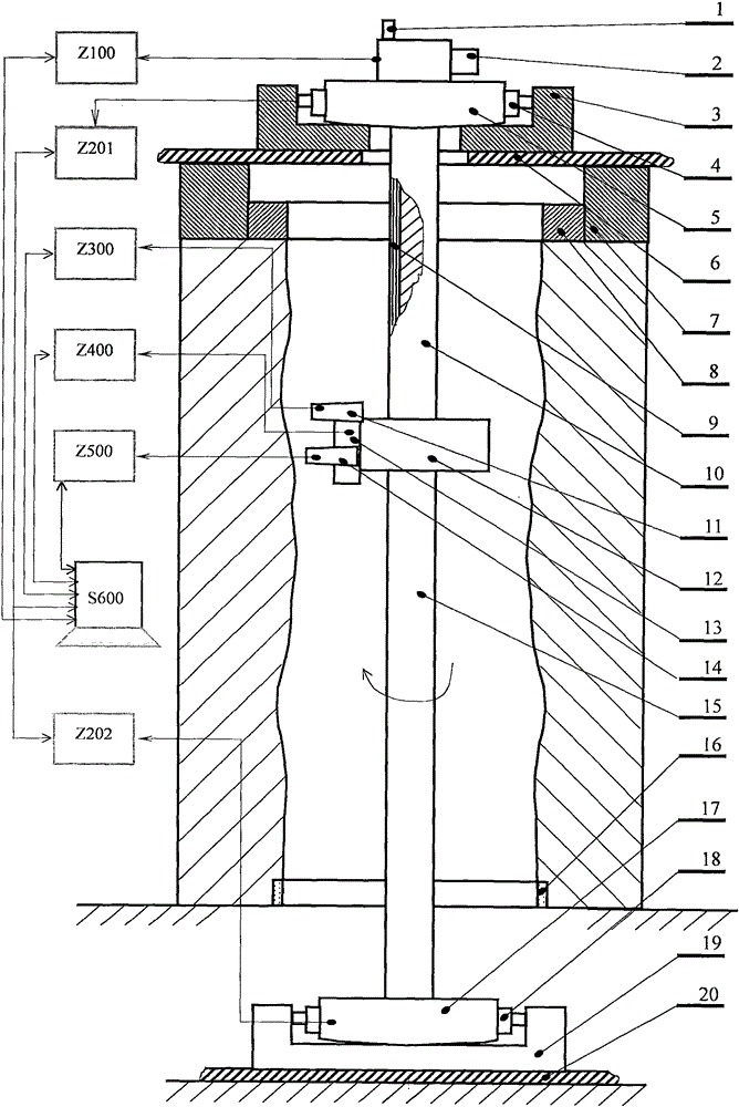
[0025] Such as figure 1 As shown, firstly, the machine tool is initially hoisted and fixed in the hole of the machined part, so that the machining spindle of the machine tool is roughly consistent with the axis of the machined hole and fixed. Secondly, the installation includes the spindle and the spindle drive device Z100, the spindle centering adjustment device Z201 and the spindle centering adjustment device Z202, the spindle position detection device Z300, the tool post axial feed device Z400, the tool post radial feed device Z500 and a comprehensive Control system Z600, etc.

[0026] Then establish the datum axis. The present invention adopts two methods for establishing the reference axis: one is to use the standard ring method, and the joint axis determined by the centers of two or more standard rings is used as the reference axis; in this method, the standard ring can also use a pre-set process The datum plane is replaced, that is, the datum axis is the joint axis es...


PUM


Abstract

The invention relates to an automatic positioning technology of a main shaft of a machine tool in field processing, which can realize automatic detection, adjustment, positioning and fastening of the main shaft in the installation and debugging process of machine tool equipment. The automatic positioning technology adopts two reference axis determination methods: one is a standard ring or process reference surface method, and combined axis determined by the centers of two or more standard rings or process reference surfaces serves as reference axis; and the other one is a method for determining the reference axis by combining horizontal measuring instruments with the standard rings or the process reference surfaces; the standard rings or the process reference surfaces are detected through scanning; data is acquired and analyzed to calculate the position of the reference axis to judge the position and the deviation of the main shaft of the machine tool; and multiple sets of main shaft position automatic adjusting and positioning devices capable of telescopically adjusting an ejector rod driving centering adjusting mechanism to generate displacements on a bearing base are designed to realize automatic adjustment and positioning of the position of the main shaft. The automatic positioning technology can be applied to such operations as installation, use, debugging, maintenance, processing, repair and detection of large machine tool equipment and parts in such fields as hydropower stations, nuclear power stations, warships, ships and mining, or can be expanded to be applied to automatic positioning of the main shaft in general hole part processing and various operation processes.

Description

technical field [0001] The patent of the invention relates to an automatic positioning technology of the main shaft of the on-site processing machine tool, which involves the automatic detection, adjustment, positioning and fastening of the main shaft during the installation and commissioning of the machine tool equipment, and can be applied to large-scale in the fields of hydropower stations, nuclear power stations, ships, ships, mining, etc. The installation, use, debugging, maintenance, processing, repair, testing and other operations of machine tool equipment and parts can also be extended to the processing of general hole parts and the automatic positioning of the spindle during various operations. Background technique [0002] The installation, use, commissioning, maintenance, processing, repair, testing and other operations of large-scale equipment and parts often cannot be handled by traditional methods. There are many difficulties for the manufacturer or the designa...

Claims


Application Information

Patent Timeline
IPC IPC(8): B23B19/02
CPCB23Q1/70
Inventor 张国根傅惠南
Owner FOSHAN XINCHENG HONGDING MACHINERY TECH CO LTD
Why Eureka
Try Eureka