
A device for quickly and neatly determining the location of a tree hole for tree planting

A neat and tree-hole technology, which is applied in the field of devices for determining the location of tree holes, can solve problems such as deviation of tree hole positions, unfavorable tree planting efficiency, and waste of time, and achieve the effects of saving time, convenient and quick operation, and reducing workload

Inactive Publication Date: 2018-11-13
杜人杰 +3
View PDF7 Cites 0 Cited by
  • Summary
  • Abstract
  • Description
  • Claims
  • Application Information

AI Technical Summary

Problems solved by technology

[0003] The purpose of the present invention is to provide a device for quickly and neatly determining the position of the tree hole for tree planting in view of the current waste of manpower and time for determining the location of the tree hole, which is not conducive to improving the efficiency of tree planting, and the position of the tree hole dug has deviations.

Method used


Image

  • A device for quickly and neatly determining the location of a tree hole for tree planting
  • A device for quickly and neatly determining the location of a tree hole for tree planting
  • A device for quickly and neatly determining the location of a tree hole for tree planting

Examples


Embodiment 1

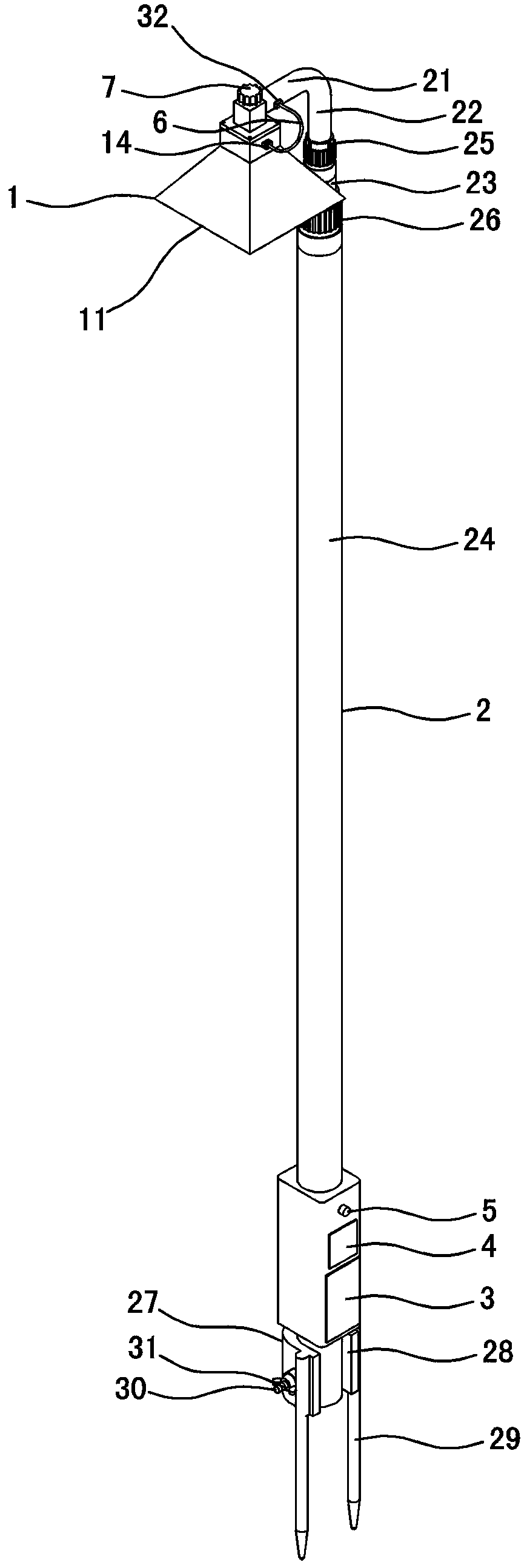
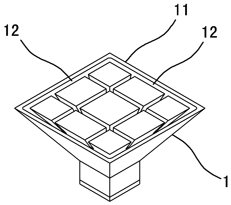
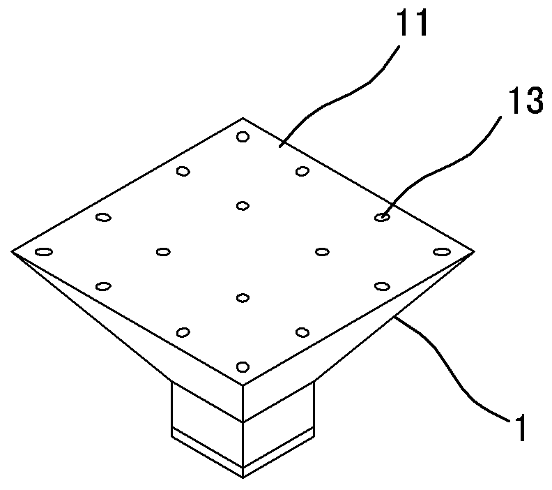
[0010] Embodiment one, such as figure 1 , figure 2 , image 3 As shown, it includes a grating projector 1, a lifting rod 2, a plurality of infrared laser diodes, a battery 3, a drive circuit board 4 and a power switch 5, and the projection port 11 of the grating projector 1 is installed downward on the upper end of the lifting rod 2 On the beam 21 arranged horizontally, the grating projector 1 is provided with multiple rows and columns of projection slits 12 for projecting grid-like light to the ground or projection holes 13 for projecting grid-like points to the ground, each adjacent row and The projection slits 12 of adjacent columns are distributed in a divergent shape with gradually increasing spacing from top to bottom on the grating projector 1, and the projection slits 12 located at the projection port 11 of the grating projector 1 have a wide middle spacing and gradually change the spacing on both sides. Narrow, so that the grid projected on the ground presents equa...

Embodiment 2

[0016] Embodiment two, such as Figure 4 As shown, the difference from Embodiment 1 is that the battery 3, the drive circuit board 4 and the power switch 5 are respectively installed on the grating projector 1 (the battery 3, the drive circuit board 4 and the power switch 5 are installed on the grating projector 1 so that Wiring is simpler and more convenient), it also includes a remote controller 8 and a remote control receiver installed on the grating projector 1, the two input terminals of the power switch 5 are respectively connected to the positive and negative poles of the battery 3, and the two output terminals are respectively connected to the remote control receiver , the remote control receiver is connected with the driving circuit board 4, and the driving circuit board 4 is connected with each infrared laser diode. This structure can realize remote control on and off of each infrared laser diode, and the operation and use are more convenient.

[0017] Working princ...


PUM


Abstract

The invention relates to a device used for rapid and neat determination of tree pit positions in tree planting. The device comprises an optical grating projector (1), a lifting rod (2), and a plurality of infrared laser diodes; the optical grating projector (1) is arranged on the upper end of the lifting rod (2); the optical grating projector (1) is provided with a plurality of rows and columns of projection slits (12) or projection holes (13); the projection slits (12) and the projection holes (13) are dispersed on the optical grating projector (1) in a radiation gradually-changed manner; and the upper part of each projection slit (12) or projection hole (13) is provided with one infrared laser diode. The device can be used for rapid high-efficiency determination of tree pit positions; both time and labour are saved; and operation is convenient and rapid. According to the device, optical grating grid is used for accurate positioning, accurate positioning of each tree pit can be realized via optical grating projection positions; using of the device is not influenced by weather and the environment; labour and material resource are saved; tree planting cost is reduced; and working efficiency is increased greatly.

Description

technical field [0001] The invention relates to a tree planting device, in particular to a device for determining the position of a tree hole when planting trees. Background technique [0002] As the state strengthens the protection of forest resources, commercial logging has been banned, and the direction of forestry development is also changing from logging to closing mountains for afforestation. There are a large number of tree planting tasks to be completed in my country's forest areas every year. Since trees are mainly suitable for planting in spring and the time for planting is relatively short, planting efficiency is particularly important. In the process of planting, in order to ensure that the planted trees are arranged horizontally and vertically in rows and the spacing is standardized, it is first necessary to determine the location of the tree digging holes, so as to avoid inconsistent spacing between the digging holes, resulting in uneven planting of the trees. ...

Claims


Application Information

Patent Timeline
Patent Type & Authority Patents(China)
IPC IPC(8): G08C23/04
Inventor 曲跃军杜人杰赵敏李晓秀杜运长王晓静周冬跃张翼郑焕春林海峰
Owner 杜人杰
Learn More